


Other Parts Discussed in Thread: TPS2595
Hi Team,
We are finalizing one hardware design with TUSB8043A and Jetson Nano SOM. We would like to get the same reviewed by TI community, block diagram attached
Requirements: 4 Port USB hub to connect 4 USB cameras and to supply adequate power to cameras (Approx 250mA per camera)
Note: Design to support USB 2 or 3 inline with connected device's capabilities
Design details:
1. SOC_READY (SYS_RST from Jetson Nano) will enable 3V3 DC-DC to supply VDD33 for TUSB8043A after completion of proper SOM Power ON
2. VDD33 will get supplied before VDD11 as 1.1V LDO is powered using 3V3 rail
3. Active Reset scheme for TUSB8043A with a GPIO from the SOM as shown in image is selected inline with power on sequence
4. USB_VBUS is tied to 1.8V GPIO of SOM through voltage divider. Do we need to give an option to connect the same to 3.3V rail through voltage divider as shown in the image with dotted lines ?
5. Downstream power is managed with GANGED MODE since single TPS2595 is used for powering 4 devices together
6. STRAP Pins or MISC Pins
FULLPWRMGMTZ_SS_UP -- PD
(Battery charging is not mandatory. However over current inputs and GANGED control towards downstream is required)
GANGED_HS_UP -- PU
PWRCTL_POL -- PU
AUTOENZ_PD -- PU
SMBUSZ -- PD
Note: External PU & PD options are given to all PIN for maximum possibilities during bring-up
7. Current design is to make the HUB configurable through SMBUS hence tied SMBUSz to PD
Please share your advice to make the design better or if it is having any potential pitfalls.
Regards,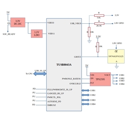
Jayasurya

