Because of the holidays, TI E2E™ design support forum responses will be delayed from Dec. 25 through Jan. 2. Thank you for your patience.

This thread has been locked.

If you have a related question, please click the "Ask a related question" button in the top right corner. The newly created question will be automatically linked to this question.

LMH1218: LMH1218 fail to output 12G-SDI 4K Video:

Part Number: LMH1218

LMH1218 fail to output 12G-SDI 4K Video:
BARCO and SONY medical displays are tested with both displays failed to display SDI video.
BARCO display prompted "no signal", and SONY display prompted "unknown".
In some rare occasions, SONY display prompted "3840x2160", which is the correct video resolution, and flashed out the distorted video image frame, then went back to "unknown" repeatedly. But after some SW reloading, SONY display went back to "unknown".
SW and HW design:
4K video source is GT transceiver of Xilinx Zynq ZU4, which is transmitting 11.88Gbps 12G-SDI video frames.
Video Format: 3840x2160 60FPS YUV422 10bit pixel.
According to GT status registers, the video transmitting is synchronized to 4K video standard timing, some like active size, sync width, front porch, back porch and so on.
At the same time, LMH1218 is working OK, CDR stays locked to 11.88Gbps SMPTE.
  • Greetings,

    I am assuming lower data rates is ok and you see this issue mainly at 12G SDI.

    I would check to make sure LMH1218 initialization is done.

    Secondly, please make sure manual CTLE setting on LMH1218 is correct.

    Another item, please make sure you are turning off the de-emphasis on the device driving LMH1218 100-ohm input.

    You can use LMH1218 GUI to change some of these parameters quickly.

    Regards,,Nasser

  • Thanks for replying.
    Sadly, it didnot work out.
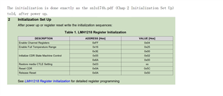
    The initialization is done exactly as the snlu174b.pdf (Chap 2 Initialization Set Up) told, after power up.
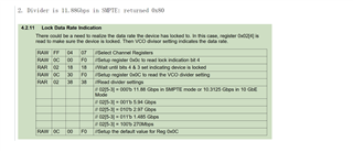
    And after CDR is locked (according to the LOCK pin), I checked register 0x02 repeatedly. 
    The register data indicated:
    1. Device is locked: returned 0x58
    2. Divider is 11.88Gbps in SMPTE: returned 0x80
    The CTLE settings didnot change anything.
    As for lower data rates, currently SW cannot apply.
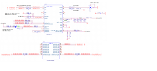
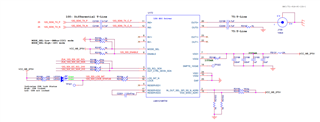
  • Lmh1218 is input from zu4 GTX,12Gbps differential signals are 100 ohm impedance matched,The circuit is as follows:

  • Hi Shaoping,

    Based on reg 0x02 = 0x58 it seems device is indeed locked. Please read HEO and VEO register values and let us know these two parameters. 

    Can you get one of the LMH1218EVM so you can check this with this board?

    Regards ,, Nasser

  • I don't have the LMH1218EVM board.

    I don't quite understand the meaning of HEO and VEO.

    my initialization CONFIGURATION: 

    register    data & mask
    0xFF        0x04 & 0x07
    0x16        0x25 & 0xFF
    0x3E        0x00 & 0x80
    0x55        0x02 & 0x02
    0x6A        0x00 & 0xFF
    0x03        0x80 & 0xFF
    0x0A        0x0C & 0x0C
    0x0A        0x00 & 0x0C

    0xFF        0x04 & 0x07
    0x31        0x01 & 0x03
    0x2F        0x00 & 0xC0
    0x0A        0x0C & 0x0C
    0x0A        0x00 & 0x0C


    and the runtime REGISTER readout value: 

    1218 0x02 lock: 0x58
    1218 0x02 vco: 0x80
    1218 0x27 HEO: 0x31
    1218 0x28 VEO: 0x40

  • Greetings,

    Given Reg 0x02 = 0x 58 it means device is locked. HEO and VEO values show about 0.7UI horizontal and 200mV vertical eye opening. Given these numbers, we should be running error free. Please refer to the LMH1218 programming guide section 4.2.12 for details.

    Please note some suggestions below:

    1). In your initialization you use a value of 0x80 for reg 0x03. You may need to use other values or you can experiment with other values. This value sets the CTLE gain. Changing this value should improve your VEO value.

    2). Please note you should be reading reg 1218.0x02 only. I don't understand why you have VCO:0x80.

    3). Given CDR is locked, we should concentrate on 75-ohm output characteristics and media. This includes return loss, cable type length used between BNC connector and camera you are using. It would be good to have LMH1218EVM or you can acquire of these boards so you can use to correlate.

    Regards,,Nasser 

  • 3). Given CDR is locked, we should concentrate on 75-ohm output characteristics and media. This includes return loss, cable type length used between BNC connector and camera you are using. It would be good to have LMH1218EVM or you can acquire of these boards so you can use to correlate.

  • when 1218 is locked to 11.88/1.001 Gbps,under what circumstance would 1218 EOM to be like closed?
    the register values of 1218 are:
    1218 0x02 lock: 0x58
    1218 0x27 HEO: 0x00
    1218 0x28 VEO: 0x00

  • Hi Shaoping,

    Register 0x02 = 0x58 shows device is locked but HEO/VEO values are 0x00. HEO/VEO values show eye is closed. Please read register 0x02 many times since i expect device to go out of lock. 

    Also, please use different CTLE settings since LMH1218 uses manual CTLE settings.

    Lastly, you can use LMH1218EVM GUI to control LMH1218 device on your board to make sure registers are setup properly.

    Regards,Nasser

  • according to snlu174b 4.2.15.1 out0 vod settings, the content of register 0x80 represents out0 peak-to-peak voltage.
    how come the content of reg 0x80 stays at 0x0, while the EOM value HEO == 0x36 and VEO == 0x40
    does this mean out0 is not transmitting any data?

    another question:
    snlu174b 4.2.12
    VEO value stays at 0x40 and not changing, the vertical eye opening is 64*3.125=200mV
    with peak-to-peak value is +/-400mV, does 200mV means the 1218 input data quality is not good enough?

  • Hi Shaoping,

    1). Please note HEO and VEO represent eye opening at the 100-ohm input after PCB CTLE equalization settings by register 0x80 - before the CDR.In summay, reg 0x80 setting is not related to the HEO/VEO values.

    2). 200mV VEO and at least 0.2UI of HEO should result in error free operation.

    Regards , Nasser