This thread has been locked.

If you have a related question, please click the "Ask a related question" button in the top right corner. The newly created question will be automatically linked to this question.

TCAN330G: TCAN330GDR

Part Number: TCAN330G
Other Parts Discussed in Thread: TCAN330

HI,

we updated our hardware from ATA6561-GAQW-N  to TCAN330 transceiver
ATA6561 is  working with +5V supply
TCAN330  is working with +3.3V supply.

Now our CAN communication is not woring with the TCAN330.

The Bus analyser  shows "Stuff Bit Errors".
This looks like some problems with the bus timing.

We us:
- Boud rate is 250 kbps
- CAN-OPEN protocoll.
- PIC32MK1024MCF100 controller.

Waveform on bus looks OK.

Are there some special timing options that we have to use with the TCAN330?

Our acutal timing is:
- Sample Point:  85%
- Propagation SementTime (nS): 1600
- Total Time Quanta(TQ)          : 20
   - Sync Segment(TQ)             :  1
  -  Propagation Segment (TQ) : 8
   - Phas 1 Segment(TQ)          :  8
   - Phas 2 Segment(TQ)          :  3
-  Synchronization Jump Width(QT): 3
- Time Quanta(ns): 200.000

Wiring of the transceiver:
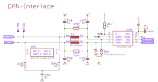
Regards
Christian

  • Hi Christian,

    Thanks for sharing this information with us. 

    There should be no needed changing for timing configuration when working with TCAN330 as opposed to the 5V CAN transceiver you listed (the loop timing is actually faster so should be less of a concern for the 3V device). The data rate is also far too slow for the small differences here to really make a difference in the data. I also don't see any issue with the timing configuration you shared here. 

    I would be interested to see the waveforms on the 3.3V CAN bus when the bit stuffing error is reported. Would it be possible to share scope shots of the CAN frames in question? I would be interested to see if you can capture the exact frame that also throws an error. This would be possible using a scope that can identify an error frame (6 consecutive dominant bits), or may be done more simply by filtering for longer dominant state with the scope trigger.

    Can you share how often these errors seem to occur? On every sent frame or or only occasionally in the system? Also let me know if there are any other errors that have been reported during this testing. Lastly, do you know how many other nodes are on the test network and what their supply voltage is? A block diagram of the CAN network might be the easiest way to share this. 

    Let me know if you have any other questions in the meantime. 

    Regards,
    Eric Schott