This thread has been locked.

If you have a related question, please click the "Ask a related question" button in the top right corner. The newly created question will be automatically linked to this question.

TL16C750E: No reception in RS485 mode

Part Number: TL16C750E
Other Parts Discussed in Thread: TMS320F28386D

Hello,

We are using the TL16C750E in RS485 mode in our design, the schematic is the following:

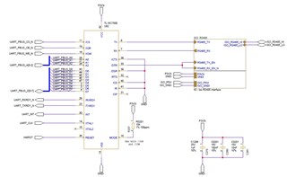
The clock is set at 25MHz and we are connected to the EMIF bus of a TMS320F28386D.

Transmitting data on the bus works perfectly, however we can't seem to be able to receive data.

We tracked down the received data down to the component RX pin and the signal seems ok to us:


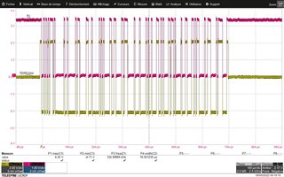
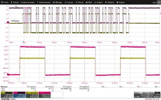
These screenshots are showing data transmission of 16 bytes at 250kbit/s (I think we are sending 0xAA, 0x01, 0x02, ...).

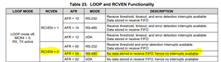
The registers configuration of the component is the following:

  • EFR: 0x10
  • FCR: 0x07
  • LCR: 0x0B
  • MCR: 0x00
  • AFR: 0xA4
  • DLL: 0x06
  • DLH: 0x00
  • DLF: 0x10

We have tried with internal loopback and we are receiving data but from the outside it doesn't seem to want to work.

Any idea/hint ?

Best regards,

Clément

  • Clément,

    Thanks for bringing this to E2E. An engineer has been notified of your post and will have a response to you by end of business 05/06/2022.

    Regards,

    Eric Hackett 

  • Hello Eric,

    Did you meant 06 May or 05 June ?

    Regards,

    Clément

  • Clement,

    How are you looking for interrupts and determining if there is data to be read? Most people use the INT pin to initialize an ISR. Your register configuration has MCR set to 0x00h which means the INT pin is never active.

    If you aren't using INT, are you polling the device instead?

    -Bobby

  • Bobby,

    We are indeed polling the LSR bit 0 but its state never changes.

    Clément

  • Hi Clement,

    Can you do a read of IER after you read LSR bit 0? I just want to double check the device isn't in sleep mode for some odd reason. (IER bit 4)

    I'd also like to see if you can enable IER bits 0 - 3 and then try reading the IIR register after the data is sent.

    "

    • EFR: 0x10
    • FCR: 0x07
    • LCR: 0x0B
    • MCR: 0x00
    • AFR: 0xA4
    • DLL: 0x06
    • DLH: 0x00
    • DLF: 0x10"

    Can you verify/read these registers after sending the data. I wanna double check that they didn't change (just want to be sure some kind of reset didn't occur)

    -Bobby

  • Hi Bobby,

    Can you do a read of IER after you read LSR bit 0? I just want to double check the device isn't in sleep mode for some odd reason. (IER bit 4)

    IER is equal to 0x01 (this is what we configured, I forgot to put that register value) in my initial post.

    I'd also like to see if you can enable IER bits 0 - 3 and then try reading the IIR register after the data is sent.

    The register is equal to 0xC1, which is not as expected as we should be having a RHR pending interrupt if the data was received.

    Can you verify/read these registers after sending the data. I wanna double check that they didn't change (just want to be sure some kind of reset didn't occur)

    EFR = 0x10

    FCR = Cannot be read, only available in write mode

    LCR = 0x0B

    MCR = 0x00

    AFR = 0xA4

    DLL = 0x06

    DLH = 0x00

    DLF = 0x10

    They are unchanged.

    Clément

  • Hi Clement,

    The register is equal to 0xC1, which is not as expected as we should be having a RHR pending interrupt if the data was received.

    I agree, this seems to suggest the RX pin isn't seeing any traffic at all.

    I've doubled checked your schematic and it appears like all of the pins are associated correctly with the datasheet pinout. 

    Can you probe the XTAL1 net before/during the RX receive transmission? I want to double check to see if it's properly toggling. 

    Lastly, can you write into the AFR register 0xB4 instead of 0xA4?

    From datasheet: "When both RCVEN and 485EN are set, the receiver stores any data presented on RX, if any"

    I believe bit 4 in the AFR is disabling the interrupt and completely disabling the RX from receiving data at all.

    -Bobby

  • Hi Bobby,

    I'll probe the XTAL1 pin but I think it was clean. Moreover we were able to send data so I think the clocking is correct.

    The datasheet wasn't 100% clear about that RCVEN bit, I rather understood it as the capability to log sent data by the component itself from further descriptions in the document.

    I'll try that either later today or tomorrow and will get back to you.

    Thanks,

    Clément

  • Good catch Bobby.

    I was honestly mislead by the whole big description from the table just before the one you posted that let me thought this bit was required for wrap around of sent data...

    Thanks for the help.

    Clément