This thread has been locked.

If you have a related question, please click the "Ask a related question" button in the top right corner. The newly created question will be automatically linked to this question.

TUSB1046-DCI: pull in the USB3 cable common voltage outoff limit

Part Number: TUSB1046-DCI
Other Parts Discussed in Thread: TUSB1046EVM, TUSB1146, TPS65987D

Hello TI team

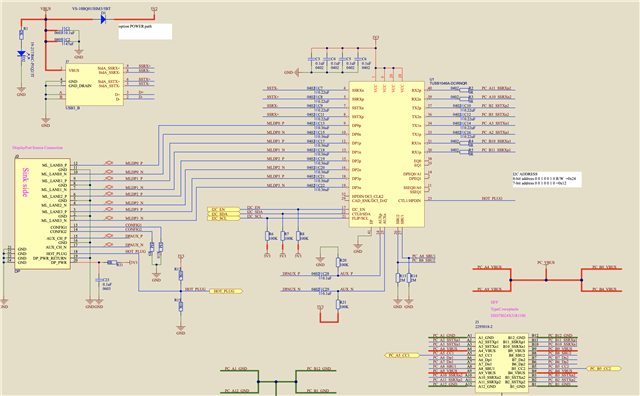
  1. There is a project that use TUSB1046-DCIRNQT,the schematic is referenced TUSB1046EVM. When connect the Displayport and USB3 at the same time, The TUSB1046 registers were configured 0x0A=0x03,0x10=0xAA,0x11=0xAA,0x12=0x02,0x13=0x00,0x20=0xAA,0x21=0x0A,0x22=0x04.The pin25(AUXn) common mode voltage is 1.57V ,and the PIN24(AUXp) common mode voltage is 0.28V. Then pull out the USB3 cable the pin25(AUXn) common mode voltage change to 2.83V, pull in USB3 cable the common mode voltage will drop down to 1.57V again. Can you help me to resolve this issue ?
  2. When remove the USB3 cable, the device (TUSB1046) can work well 4lane flipping, 4lane not  flipping,2lane +USB3 flipping ,2lane +USB3 not flipping .
  • Hi,

    Where does TX1/TX2, RX1/RX2 connected? Are they connected to a Type-C connector?

    If you are connecting to a Type-C connector, then the host already has pullup/pulldown (100k). In this case, you would leave R20 and R21 open.

    Thanks

    David

  • hello David 

    1.Thank you for your quickly reply. TX1/TX2, RX1/RX2 are connected the DOCK station or monitor. When I remove USB3 cable(j?) the DP signal  work well. Then I pull in the USB3 cable the common voltage at PIN25 will drop down from 2.8V to 1.5V , I am very confuse why the USB3 cable will influence the PIN 25 common mode voltage .

    Thanks 

    Thomas 

  • Thomas

    Have you tried to remove the R20 and R21? The 100k pullup/pulldown should already be populated on the DP source side and the 1M pullup/pulldown should already be populated on the monitor or the dock station. 

    It looks like you are using the TUSB1046 I2C mode to control the TUSB1046.

    • For I2C_EN, please use 1k pullup instead 100k.
    • For SCL/SDA, please use 4.7k pullup instead 100k. 

    Do you have a PD controller that programs the TUSB1046 through the I2C bus? 

    Thanks

    David  

  • Hello  David

    1. Sorry for  delay reply .

    2.I had follow your instruction remove the R20 and R21, change 100K to 1k and 4.7k, and  changed C28 and C29 to 0R ,  but it still had same result .

    AUXn common  mode voltage still change to 1.59V  when insert the USB3 cable.

    3.I change TUSB1046DCIRNQR to TUSB1146RNQR there are had same phenomenon.

    4.There is a TPS65987D PD controller,but still use EC to conntrol TUSB1046 or TUSB1146.

    5.below is the debug  record .

    USB3IN PD message.zip

  • Hi,

    Can you please probe the CC1, CC2, and HPDIN voltage for the failing case?

    Below is the CC voltage values that a Source shall use to detect what is attached based on the USB Type-C Current advertisement (Default USB, 1.5A @ 5 V, or 3.0 A @ 5 V) that the Source is offering.

    Thanks

    David

  • Hello David

    1.I had probe the HPDIN PIN it will drop the voltage from 3.3v to 0v at the failing case or ok case. And catch the PD massage both are same when negotiated.

    2. When config TUSB1046 or TUSB1146 4lane mode or 2lane+usb, the common mode voltage will drop down  from 2.8V to 1.5V when insert the USB3 cable, when remove the USB3 cable the common mode voltage will rising up to 2.8V. Above actions there was't any PD massage negotiated.

  • Hi,

    Can I please take a look at the full schematic and layout? 

    I honestly don't see how inserting the USB3 cable would impact the AUX voltage. The PD controller is not aware the insertion of the USB3 cable and should not change its TUSB1046 configuration (register 0x0A). The only thing I can see that will impact the AUX is the VBUS and ground connection from the USB3 connector.

    Do you have the TUSB1046 thermal pad soldered to the PCB ground?

    Thanks

    David

  • Hello  David

    1.Thanks for your advice.

    2.There is a SMT mistake that B5 is short B6, so it make the sink side error.

    Thanks

    Thomas

  • Thomas

    Thanks for sharing the good news, I am glad you found the issue.

    Thanks

    David