This thread has been locked.

If you have a related question, please click the "Ask a related question" button in the top right corner. The newly created question will be automatically linked to this question.

THVD1550: pull up or down the pin_R while the VID is between VIT-/+?

Part Number: THVD1550

Hi Expert,

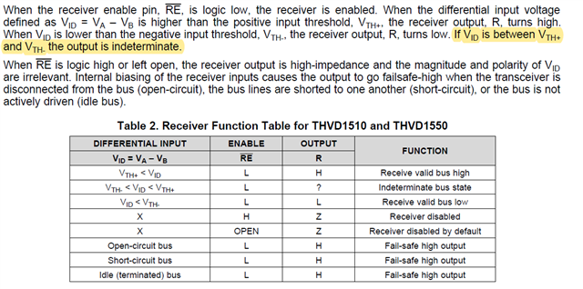
According to the datasheet p.15, If the VID is between VIT+ and VIT-, the output is indeterminate.

The question is that do you recommend to pull it up or down to fix the status when VID is between VIT+/-?

Could I pull it up or down?

Or just leave it along?

BR,

Aaron Chen

  • "Indeterminate" means that the THVD will actively drive the output either high, or low, or even both (oscillating) if the input is floating in this range for a long time; a pull-up/-down resistor would not help at all.

    The thresholds are designed so that a VID in the invalid range will occur only for a short time while switching. You should not need to care. Is there a specific concern that a voltage between −200 mV and −20 mV can happen?

  • Hi Aaron,

    I will preface this by saying - this device has internal fail-safe protections which help the device consider the differential voltage of 0V to be active high so that in open/idle bus states the output isn't undefined. the negative threshold is -200mV minimum and the max positive threshold for this device is -20mV.  If your system isn't very noisy and a margin of 20mV in idle/open conditions is acceptable - you do not need to do anything. If you would like added noise margin using 2 resistors for the entire system can add external fail-safe biasing - please see below for more information. 

    To prevent indeterminate bus states (such as bus idle or bus open conditions where VID may be closer to 0V) you can use fail-safe biasing - we have a detailed application note here: https://www.ti.com/lit/an/slyt324/slyt324.pdf that goes through the process - I have summarized the process below.

    The above diagram shows the RS-485 bus with the two termination resistors  between the A and B pin labeled R_T1 and R_T2, the eq. input impedance of all RS-485 transceivers on A and B labeled as R_INEQ (For the THVD1550 - which supports 256 nodes as stated on first page - the input resistance per device on the A or B pin is 96K (1/8 unit load)) R_INEQ is the paralellel combination of all input resistances on the line - so for the 1550 if you have 2 devices R_INEQ = 48K and if 3 devices R_INEQ = 32K and so on. R_FS is the fail-safe resistor these resistors will help keep the idle voltage above threshold. R_T1 and R_T2 are typically set to 120 Ohms and then from there solving for R_FS where V_AB >= 200mV during and idle/open bus state. In cases with only a couple devices on the line the R_INEQ value for the 1550 will be quite large and won't really affect much and they can just be ignored - (in systems with many more than 2 or 3 nodes R_INEQ will have a larger effect and should be considered please see application note for more information here) 

    If we assume R_INEQ is >> than every other resistor in the system (appropriate approximation in low node systems) and if we take the parallel combination of R_T1 and R_T2 to be R_T (as this is how the driver will see this resistance) the equation for V_AB = (V_CC * R_T)/(R_T + R_FS_B + R_FS_A) where when solving for the fail safe resistors --> R_FS_B + R_FS_A = ((V_CC * R_T)/V_AB) - R_T. Now R_FS_A and R_FS_B can be chosen to meet this expression. The only limit is that the driver on either the A or B pin can only see a minimum of 375 Ohms to ground (with all sources but the driver shorted due to superposition) - this means that the R_FS_A value when in parallel combination with input impedances on the A line and the R_FS_B value when in parallel combination with input impedances on the B line must be >= 375 Ohms to prevent overstressing the driver - in low node systems this typically just means the fail-safe resistors should be >= 375 Ohms.

    Couple notes:

    1. Fail-safe resistors only need to placed on 1 node in the system - these resistors apply to the entire bus.

    2. This method assumes termination between A and B nodes at both ends of the system

    3. 2-3 node systems you can ignore R_INEQ for the THVD1550, above that be sure to include that in the design.

    Final thoughts - 

    If your concern is that the signal is being attenuated too much this will not help recover the signal - this is for conditions when the bus is in an idle or open state and V_ID is close to 0V. The THVD1550 has internal fail-safe as well which means that a bus voltage of 0V is considered active high to help with idle / open state conditions. However adding the external network as mentioned above could add more noise immunity as the undefined state is only -20mV away for an idle condition so noise could cause glitches and the above network could improve noise immunity. 

    Please let me know if you have any other questions!

    Best,

    Parker Dodson