This thread has been locked.

If you have a related question, please click the "Ask a related question" button in the top right corner. The newly created question will be automatically linked to this question.

SN75HVD12: Replacement to SN75HVD12D

Part Number: SN75HVD12
Other Parts Discussed in Thread: THVD1410, THVD2450, THVD1450, , ISO15

Hi Team,

Our customer is looking for a replacement to SN75HVD12D. The product page of SN75HVD12D suggested THVD1410, THVD1450 and THVD2450. According to our customer,

We have been trying some alternatives to this IC in a BUS RS485 communication and somehow this is the only IC that works: in conjunction with switching power supplies, this is the only one that "resists the disturbances". Is it possible to pinpoint what makes it so special, especially for finding a TI replacement?

Regards,

Danilo

  • Hi Danilo,

    What kind of problems are you seeing from the other IC's you have tried with a switching power supply? I am asking because I am trying to find what the problem signature may be looking like as using a SMPS is pretty common practice for RS-485 transceivers.

    Are you using supply decoupling capacitors at the VCC pins or the other transceivers (these are used to help dampen oscitations from long wires/switching noise on power line)? 

    If possible can you share what type of SMPS is being used, type would be good - but part number would be better if possible. 

    Please let me know so I can maybe dig a bit deeper down to what is possibly causing this issue and some possible resolutions.

    Best,

    Parker Dodson

  • Hi Parker,

    Thank you for your response. According to our customer,

    we are using the SN75HVD12D in emergency luminaires applications: many lamps (up to 255) are connected on the same RS485 bus and communicate with the central unit. This architecture has been in use for many years with no problems.
    Each luminaire has a switching power supply (for charging the battery) which is a standard isolated flyback architecture. For example we use the VIPER27LN from STMicroelectronics or FSEZ1016 from Onsemi.
    With the SN75HVD12D IC we never experienced any communication issues with the central unit.
    With other models, for example EXAR SP3072EEN, which is apparently equivalent, we found out that the "reception" becomes faulty.
    I noticed that, when the switching power supply is operating, our luminaire cannot receive the message from the central unit. I verified that when the bus wire is long and the bus is idle I measure (with an oscilloscope) activity on the "R" signal (it goes up and down).
    When I turn off the AC power of the luminaire (power is now from battery), the communication resumes correctly.
    Moreover, when the AC power is on and I remove the Y1 capacitor between primary and secondary (used for EMI purposes), the communication resumes correctly.

    Therefore, I prescribed to only use SN75HVD12D which never gave us problems, but now it is becoming obsolete.
    I would like to select a replacement part but TI website says nothing about it. And, in selecting one of your IC's, which parameter is the most important to avoid the problem described above?

    Regards,

    Danilo

  • Hi Danilo,

    Thank you so much for all of the information.

    So honestly I think the spec that would be most helpful in this situation is one we don't spec on RS-485 devices - it would be PSRR (power supply rejection ratio) - as mentioned above this typically isn't a concern in most applications that's why we don't spec this parameter in our devices at the moment. It's also not super common in this application area of the industry as well.  This is because the A and B pins directly source their signal from VCC so it leaking into the A/B line is probable. 

    Initially I thought it could be fail-safe of the SN75HVD12, which essentially means that the differential thresholds are all < 0V - the HVD12 max positive going threshold is -10mV and maybe the noise from the power supply was low enough not to cause a switch - however the other part that was used that had issues also has fail-safe thresholds that have more margin than the HVD12 which makes me think it isn't the main issue (however how the other part defines its margins leaves way more ambiguity than ours so it could be partially the reason)

    With that being said there are potential  ways to potentially fix this problem with a new device.

    First - what is the RS-485 bus max data-rate - is it above 500kbps? 

    Second - depending on data-rate required some filtering could be added - but this is very much dependent on the data-rate as the flyback converters listed have relatively  lower switching speeds so it could very much be around data rate  or lower so filtering may not be a great option.

    Third - I still think devices with internal failsafe's are best practice - which is the VIT+ is less than 0V and VIT- is less than VIT+ by Vhys. This can also be added externally with the use of 2 resistor that will apply to the entire bus  (where internal only applies to device that has internal fail-safe) - this can help improve noise immunity of the receiver - application note how to size resistors here:  https://www.ti.com/lit/an/slyt324/slyt324.pdf. This can help reduce noise caused by long lines/idle buses etc. 

    4. What supply decoupling has been used on the IC's - as increasing this capacitance can help reduce noise going into the device.

    5. While I'd imagine this is far from ideal - but a way that will definitely help reduce is to clean up the SMPS with an LDO - I understand this is probably not the preferred option at all but with lacking information on power supply rejection performance it is a way to just prevent the problem from occurring.

    Please let me know the data rate of the application and I will be able to give you a best bet of parts and I'd highly advise looking into possibly getting a few sample units to test/prototype with in the system to see if there if they are working. I will say our newer parts shouldn't have really degraded the power supply rejection performance and it should perform similarly to this device, but since it is unknown on our parts its hard to give a definite answer.

    Please let me know and I will see what parts are the best bets.

    Best,

    Parker Dodson

  • Hi Parker,

    According to our customer.

    The data rate that we are using is 9600bps (if you are interested we configure our UART for 8N2).

    I also had the same impression that you mention: does it have to do with the threshold, with the hysteresis?

    And how do we interpret the specification of Exar? Your part is very specific about the electrical structure of the receiver, the Exar is not.

    Considering that eliminating the Y1 capacitor improves the situation, it makes me think that a (common-mode) disturbance coming from earth couples with A and B originating an unwanted change-of-state during bus idle moments.

    By the way, you might find useful to know that I had basically the same problem by trying the Analog Devices ADM3485E, even though I realized they are not exactly the equivalent, because the ADI is unitary load, not 1/8 load.

    Regards,

    Danilo

  • Hi Danilo,

    Thanks for the extra information!

    For the EXAR part - it seems to state that both thresholds are within what they spec in their "threshold" category and the thresholds are separated by Vhys - so there is more ambiguity, but it does seem to have higher noise rejection with its thresholds lower than ours.

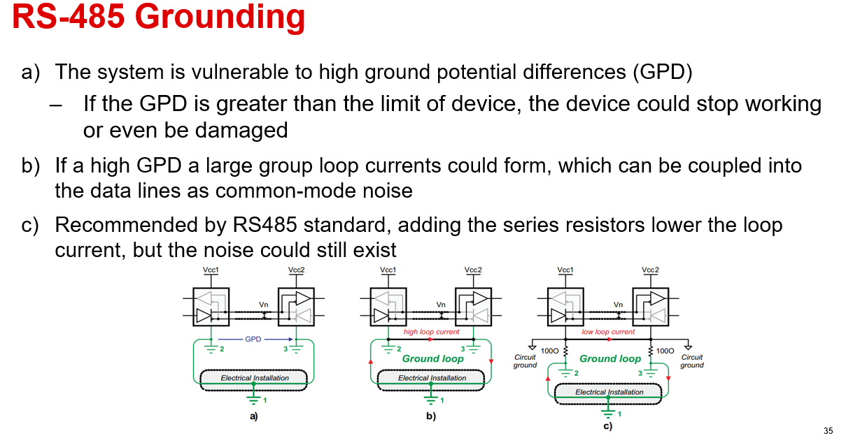
    With the extra testing you have done and the Y capacitor being removed resolves the issue I think it may be a high loop current causing common noise to be generated on the lines - it is a known obstacle in RS-485 design and symptoms do somewhat fit the issue area. 

    Essentially if this one of the problems separating the transceiver ground from the ground of the power supply using a low value resistor can help dampen common mode noise experienced by the device. As said previously how much rejection our devices have isn't typically spec'd - but at the same time solutions like above + fail-safe resistors to bias the bus and resist noise in open/idle conditions are a way to fight the extra common mode noise.

    I don't think more filtering is the best option due to the higher frequency components of the data signal (even at 9600 bps) is dominated by transition times which most likely will be above SMPS switching frequency of the devices listed and with a lot of nodes on the line adding extra components may prove unproductive.

    I think with all the data I have that you have shared - I think its "high" ground current loops that are contributing to the noise. by separating grounds - so that it lowers the ground current like above figure  common mode noise on the bus should be reduced and the bus will be more robust - regardless of part because as mentioned we don't really have a spec for how much "noise" the part rejects - just what causes noise and the general solutions for them.

    Please let me know if this is a potential option for the system - at least at a test level because I think this is probably the safest bet (when paired with our modern transceivers).

    Best,

    Parker Dodson 

  • Hi Parker,

    Here is the feedback of our customer,

    Thank you so much for the explanation so far.

    I will look into it but I forgot to mention that our products are Class-II, i.e. don't have a direct connection to common earth.
    Therefore the dc resistance to earth should be very high, it is just parasitic capacitance, so I don't really see how the high-loop-current scenario could apply, even if something is certainly related to the earth. What is I increase the series resistance on A and B? Aso of now they are 10 ohm..

    Moreover, what is strange is that the purpose of the Y1 capacitor is to keep the disturbance "whitin" the boards, i.e. it's there to prevent disturbances to be sent to the power lines and come back from earth, so it should be better with Y1 and worse without....but it's the opposite...

    Apart from the analysis of the problem, could you give us an advice on the proper replacement for the SN75HVD12D? We have a case-study installation in which we could verify the performance of the alternative part (there are certain nodes which work with SN75HVD12D but don't work with the other parts, so we could experiment there).

    Regards,

    Danilo

  • Hi Danilo,

    Based on everything shared - there is most likely common mode noise. Since you can't break the ground loop since its a class II device - why there is more ground current with the Y capacitor - I am not sure, but I am not an expert with flyback converters - the reality is that it seems to be there.

    There are a couple options:

    1. We don't spec the power/common mode rejection on our standard RS-485 - the parts originally listed in the thread (THVD1410, THVD1450 and THVD2450.) are the best bets as they are most similar - but a prototype with those parts would need to be tested because we don't have data to support this spec completely. The parts that are best suited for common mode noise rejection is our isolated line of parts (see point 2). 

    2. If there is separate logic and bus supply available our isolated RS-485 transceivers gain high common mode noise immunity by breaking the ground loops between logic/bus supplies. They are not pin to pin compatible and based on the part used the best bets in this area would be ISO15 or a part from the ISO14xx line - however supply may still be an issue for all the parts. 

    Those really are the options that I see that are possible moving forward. Either try similar parts or change the design to support an isolated transceiver as I don't think the initial design would easily fit the isolated transceiver.  I understand neither are ideal - but that is the best we have at the moment for an application with this issue.

    Please let me know if you any other questions on the listed parts above - but as mentioned these are the best options with what information we have moving forward.

    Best,

    Parker Dodson