This thread has been locked.

If you have a related question, please click the "Ask a related question" button in the top right corner. The newly created question will be automatically linked to this question.

TCAN1167-Q1: tPOWER_UP

Part Number: TCAN1167-Q1

Hello team,

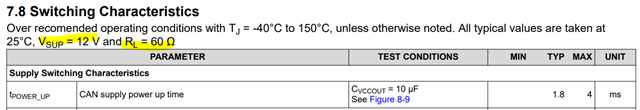
Regarding tpower_up, the test condition is CVCCOUT=10uF.

When if this CVCCOUT is changed, what has become of tpower_up?

Do you have some equation to calculate tpower_up?

Thanks.

Regards,

Hirata

  • Hi Hirata-san,

    I see you posted a few related questions around the same time, so I'll address them all here and remove the other posts. 

    Q1. When if this CVCCOUT is changed, what has become of tpower_up?

    tPOWER_UP defines the delay between when Vsup rises past 4.5V to when Vccout reaches 90% of its final value. Because the rise-time of the Vccout supply is dependant on the capacitance of the supply rail, we define this behavior at a given output capacitance. If this output capacitance is increased, the rise-time of the Vccout voltage will increase and therefore the effective tPOWER_UP will be greater. The amount that this time increases will depend on many factors including the Vsup voltage level and rise time. We do not provide an equation to calculate such effects as the specification is based on device observations under certain conditions. If a customer plans to have significantly different external conditions, the most accurate results for expected behavior would be to observe the rise-time in an experimental test. Evaluations modules are available for TCAN1167 if the customer wishes to conduct such a test. 

    Q2. How long does it take for the TCAN1167-Q1 to output the VCCOUT after the WAKE pin rising/falling edge in the Sleep mode?(min, typ, max)?

    The delay between a registered transition on the WAKE pin and the device transition into Standby mode (INH=high) is defined by tWAKE as 40us. At this time, the Vccout supply will also be enabled and start to rise. The rise-time of this supply is dependant on the output capacitance, but will likely take on the order of a couple of milliseconds. 

    Q3. Do you have the response time (min, typ, max) of the blow state transition by SPI communication?
    Standby Mode → Normal Mode
    Normal Mode → Standby Mode
    Standby Mode → Sleep Mode

    This timing is not characterised for TCAN1167. However, from my experience they are on the order of around 100us - 200us maximum. 

    Datasheet timing specifications are created based on observational data from device characterisation. If a test was not conducted during this characterisation, we cannot specify a min, typ, max timing for the behavior. When we receive inquiries like these on certain behaviors that were not included during characterisation, we can provide estimates and approximations based on individual measurements or experience. However, because these values do not come from characterisation data we cannot guarantee such values. 

    Let me know if you have any more questions.

    Regards,
    Eric Schott

  • Hi Eric-san,

    Thanks for your answer.

    Let me discuss this answer with my customer.

    I appreciate your support.

    Regards,

    Hirata

  • Hi Eric-san,

    I got feedback from my customer.

    Q1
    Customer is investigating to change the CVCCOUT from 10uF to 100uF.
    Do you have the actual measurement data with CVCCOUT = 100uF?
    Even if CVCCOUT is any other value, that would be helpful to understand how much impact does this CVCCOUT cause.

    Q2
    Do you have the actual measurement data with CVCCOUT = 100uF?
    Even if CVCCOUT is any other value, that would be helpful to understand how much impact does this CVCCOUT cause.(if you have 2 data for 2 different CVCCOUT that would be helpful for customer)

    Thanks for your support.
    Regards,
    Hirata

  • Hi Hirata-san,

    Our characterisation data only includes the one data point at 10uF. We would be able to take some bench measurements for 100uF to give a rough estimate of device behavior here, but this would not be across temperature or multiple lots.

    What is the timeline on the customer's decision? I would be able to complete these measurements by the end of next week (May 10th). Let me know if this timeline works or if the customer would prefer to take such measurements on their own setup. 

    Regards,
    Eric Schott

  • Hi Eric-san,

    Thanks for your suggestion.
    Yes, End of next week is no issue for customer.
    Regarding Q1 and Q2, Please evaluate 1 unit with output capacitor = 100uF under room temperature. That is enough now.
    Thanks so much for your support.

    Regards,
    Hirata

  • Hi Hirata-san,

    I was able to complete this testing early. I found that with a 100uF load on Vccout, the effective tPOWER_UP time was around 2.0ms at room temperature. I've sent you the detailed measurement data in an email. Let me know if this is sufficient for the customer's requirements. 

    Regards,
    Eric Schott

  • Hi Eric-san,

    Thanks so much for taking the data very fast!
    Q1 is resolved.

    Regarding Q2, how to consider? Do you take additional data or should we estimate the time from the results of Q1?
    There is twake(min)=40us specification in D/S, but it does not means the time from wake rising/falling edge to the 90% of the VCCOUT.
    But as you said the state transition takes 100-200us in general.
    Therefore are we able to estimate like below?

    10uF case: 783us + (100 to 200us) = 883us to 983us
    100uF case: 2023us + (100 to 200us) = 2123us to 2223us

    I appreciate your support.

    Regards,
    Hirata

  • Hi Hirata-san,

    Your idea here is right, but I think the tmode_slp_reset time would be better applied here than twake. 

    The time between a WUP or LWU event and when INH asserts high (tmode_slp_reset) is specified to be 50us maximum. This also represent the delay between such a wake event and when Vccout becomes active (with some margin for INH rise time). Taking into account the rise-time of the Vccout supply at the measured capactive loads, we can add these times together to get an estimate of the combined delays:

    10uF load:   800us + 50us ~= 850us
    100uF load: 2000us + 50us ~= 2050us

    Is this the condition that the customer is looking for? Do you know if there is a requirement for Vccout response time from a wake event? Or are these questions to estimate the expected response time of the system?

    Regards,
    Eric Schott

  • Hi Eric-san,

    I understood. Thanks for the suggestion.

    Yes this is the customer looking for, and in my understanding, my customer just would like to estimate the response time first.

    I appreciate your support!!

    Regards,

    Hirata

  • Hi Eric-san,

    Sorry for asking you again and again.

    Customer is wondering why the the measurement data(0.783ms) and typical spec of tPOWER_UP (=1.8ms) is so different.

    Do you know why?

    Test condition was a bit different from the one specified in D/S?

    What was the VSUP and RL respectively in you test?


    Thanks.

    Regards,

    Hirata

  • Hi HIrata-san,

    I was interested by this difference as well. I used the same Vsup (12V), but did not include a bus load on CANH and CANL. This may be where some of the difference comes from as my setup did not have the extra load on the Vccout supply which is also used by the CAN transceiver. However, I think it's quite likely there were other differences in the setup as I was testing this on an EVM. When such testing is done for characterisation, it is done on high-end automated test equipment that is a much more controlled environment than an evaluation tool. In addition to this, datasheet values typically build in some healthy margin to ensure all corners of operational conditions are covered well. 

    I think the variance seen in my measurement values are representative of the expected difference given a larger capacitive load in an application. However, these one-off measurements are very specific. The datasheet values need to guarantee device behavior, so the maximum expectation must be different. 

    Regards,
    Eric Schott

  • Hi Eric-san,

    Thanks for your detailed explanation.

    I understood.

    I will close the customer question with your answer.

    I appreciate your support.

    Regards,

    Hirata