


Hello,
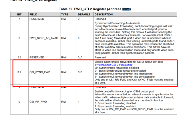
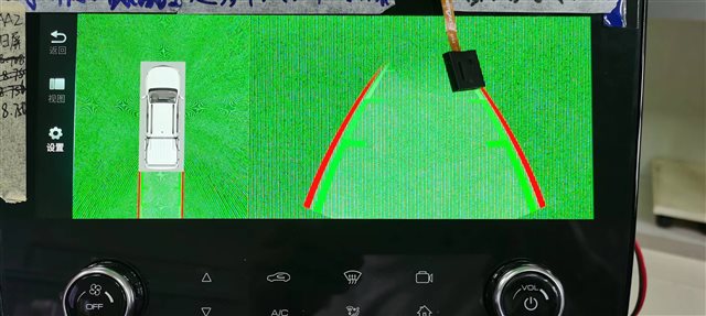
One customer used DS90UB962 for their automotive application. He need to set up 30MHz frame sync with cameras connected DS90UB933. The frame sync mode is basic synchronized forwarding mode, and 0x21=0x14. Now the GPIO1 of cameras have generated 30Hz frame sync square waveform, but when he switched reversing car with full view, it would appear green screen and columnar stripe. What is the reason? The back channel bandwidth is 2.5Mbps, 0x1F=1.6Gbps, the data type is also correct.
Below is his configuration:
ds90ub962_i2c_write(0x01, 0x02);//reset all digital part
SENSOR_MSLEEP(20);
ds90ub962_i2c_write(0x0C, 0x0F); //I2C mappings............port EN
ds90ub962_i2c_write(0x1F, 0x00); //
ds90ub962_i2c_write(0x4C,0x01); //# RX0
ds90ub962_i2c_write(0x6E,0xA0); //# BC_GPIO_CTL0: FrameSync signal to GPIO1
ds90ub962_i2c_write(0x4C,0x12); //# RX1
ds90ub962_i2c_write(0x6E,0xA0); //# BC_GPIO_CTL0: FrameSync signal to GPIO1
ds90ub962_i2c_write(0x4C,0x24); //# RX2
ds90ub962_i2c_write(0x6E,0xA0); //# BC_GPIO_CTL0: FrameSync signal to GPIO1
ds90ub962_i2c_write(0x4C,0x38); //# RX3
ds90ub962_i2c_write(0x6E,0xA0); //# BC_GPIO_CTL0: FrameSync signal to GPIO1
ds90ub962_i2c_write(0x19, 0x01); //FS_HIGH_TIME_1
ds90ub962_i2c_write(0x1A, 0x14); //FS_HIGH_TIME_0
ds90ub962_i2c_write(0x1B, 0x09); //FS_LOW_TIME_1
ds90ub962_i2c_write(0x1C, 0xbc); //FS_LOW_TIME_0
ds90ub962_i2c_write(0x18, 0x01); //ENABLE FRAME SYNC
ds90ub962_i2c_write(0x4C, 0x01); //page to port RX0
ds90ub962_i2c_write(0x58, 0x58); //enable passthrough
ds90ub962_i2c_write(0x5D, 0xB0); //imager slave ID = 0x30
ds90ub962_i2c_write(0x6D, 0x7f); //'set input mode
ds90ub962_i2c_write(0x4C, 0x12); //page to port RX1
ds90ub962_i2c_write(0x58, 0x58); //enable passthrough
ds90ub962_i2c_write(0x5D, 0xB0); //imager slave ID = 0x30
ds90ub962_i2c_write(0x6D, 0x7f); //'set input mode
ds90ub962_i2c_write(0x4C, 0x24); //page to port RX2
ds90ub962_i2c_write(0x58, 0x58); //enable passthrough
ds90ub962_i2c_write(0x5D, 0xB0); //imager slave ID = 0x30
ds90ub962_i2c_write(0x6D, 0x7f); //'set input mode
ds90ub962_i2c_write(0x4C, 0x38); //page to port RX3
ds90ub962_i2c_write(0x58, 0x58); //enable passthrough
ds90ub962_i2c_write(0x5D, 0xB0); //imager slave ID = 0x30
ds90ub962_i2c_write(0x6D, 0x7f); //'set input mode
ds90ub962_i2c_write(0x4C, 0x0F);
ds90ub962_i2c_write(0x0F, 0x00); //'disable GPIO input
ds90ub962_i2c_write(0x4C, 0x0F); //
ds90ub962_i2c_write(0x6E, 0x00); // 'set GPIO1 (nRESET) and GPIO0 (FSIN) to 0 for all four camera
ds90ub962_i2c_write(0x4C, 0x01); // 'set GPIO1 of camera 0 to 1
ds90ub962_i2c_write(0x6E, 0xAA); // '
ds90ub962_i2c_write(0x4C, 0x12); // '
ds90ub962_i2c_write(0x6E, 0xAA); // 'set GPIO1 of camera 1 to 1
ds90ub962_i2c_write(0x4C, 0x24); // '
ds90ub962_i2c_write(0x6E, 0xAA); // 'set GPIO1 of camera 2 to 1
ds90ub962_i2c_write(0x4C, 0x38); // '
ds90ub962_i2c_write(0x6E, 0xAA); // 'set GPIO1 of camera 3 to 1
