This thread has been locked.

If you have a related question, please click the "Ask a related question" button in the top right corner. The newly created question will be automatically linked to this question.

TCAN334: CAN BUS Wire

Part Number: TCAN334

Hello TI Support Team,

Good day

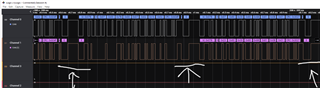
We are using 150 meters non-twisted,non-shielded 22 AWG Teflon wire for CAN Communication. During data transmission we are getting  few bits of data frame error . We are using 100K baud rate. Next to CAN high and CAN low wire we also have GND and PWR(12V) wire next to them

Could you provide me with any suggestions to fix this problem.

Thanks

  • Hi Bhanu,

    The errors in the analyser plot here appear to be NACK errors. This occurs when a CAN transmitter does not see an dominant in the acknowledge field from any receiving nodes. Are there any active receiving nodes in the setup you're testing here?

    In order to help suggest the best solution, would it be possible to provide analog scope shots of the CANH and CANL lines during a transmission? This would help us see how clean the waveform is and if there is a specific problem with attenuation, ringing, or transition timings. If possible, please include the TXD and RXD digital signals of the transmitting node as well. 

    Regards,
    Eric Schott

  • Hello Eric,

    We do not have an analog scope...

    The thing is we are transmitting data every 100ms . In short distance communication(20M) the data is being received perfectly. 

    But in long distance communication(150M) some data that is being transmitted is not being received at the other end.

    Could you provide possible reasons, why this might be occurring .The information about the wire being used is mentioned in my previous post.

    Thanks

  • Hi Bhanu,

    There are several reasons why a longer cable network may cause signal disruption. The primary reasons would be signal reflections and ringing in the larger network caused by parasitics, increased fall-times of the CAN signal due to increased parasitic capacitance, and the propagation delay introduced by the network makes the total loop delay of the system larger than the bit-width of the operational data rate. I believe the first two mentioned here would have the most impact on your described setup. We would be able to see which of these is most significant if we were able to monitor the analog voltages of the signal during data transmission. Knowing which of these is the cause will help us recommend a solution. The easiest solution will likely be reducing the data rate of the transmission so that the signal is ness susceptible to ringing and long transition times. 

    After taking a second look at the logic shot, it looks like you are showing both the TXD and RXD signals. It appears that the RXD line (lower) is remaining dominant (low) in many cases where the TXD signal is recessive (high). This is an error when it occurs in the middle of a frame and should be caught by the transmitting CAN controller. This is either being caused by the receiving node driving an error frame during the transmitted data frame, or by the CAN bus not falling to a recessive state between dominant bits. It is difficult to say which without more information on the CAN bus or what errors are being reported by the transmitting and receiving nodes. Do you know if it would be possible to get any of these details from the test setup?

    Regards,
    Eric Schott