This thread has been locked.

If you have a related question, please click the "Ask a related question" button in the top right corner. The newly created question will be automatically linked to this question.

DS90UB960-Q1: DS90UB960-Q1EVM

Part Number: DS90UB960-Q1
Other Parts Discussed in Thread: USB2ANY, , , ALP, DS90UB953-Q1, TIDA-020002

Is the USB2ANY tool necessary to set up the DS90UB960-Q1EVM?   Will any usb with compatiable connections work?  Currently it seems to function as normal but we are not able to achieve our goal.  We made a custom interface from J1 to the MIPI.

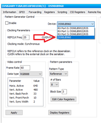
We are trying to use the DS90UB960-Q1EVM to connect to a Rasberry p4 Model B and dispaly video over the Mipi-CSI-2 Camera input and the Pi isn't detecting the camera.  Analog launch pad is detecting the serializer and a good 1920x480 video though.

Thanks

  • Hello,

    The DS90UB960-Q1 EVM has a built in USB2ANY bridge connector that can be used with any USB to mini USB cable connection or a I2C host controller. One exception is that the host controller must support clock stretching. This means that the USB2ANY tool is not the only option or method to set up the EVM board.

    If analog launch pad is detecting the device and functioning normal then your connection with the EVM is good. Are you seeing an issue with 960 EVM?

  • looks like the EVM is responding to the USB as I see I2C data when I apply Change in ALP.  I am trying to connect this to a Jetson Nano now as it was not being detected by the rasberry PI.  I clicked the Pattern Generator tab and enabled the DS90UB960 to output 640x480 color bars but the image is still not being detected my the Jetson nano.  Can you advise if their is a additional step I am missing?  thanks

  • Hello,

    There are a few variables within the Pattern Generator tab that need to be set according to your display and application such as bar size. If these values are not set accordingly they could cause an issue. Section 7.5.12 (Pattern Generation) of the datasheet explains and includes examples for how to calculate the specific values. Additionally, if you go to the information tab within ALP in the Current RX Port Status box the pass status, horizontal bytes, and vertical lines information can verify if any data is being seen on the port. Are you still connecting the EVM via J1 with this configuration? 

  •  Thanks, I had a register configured wrong and now see good signals on the O-scope for the CSI-Do/CSI_D1/CSI_CLK pairs. just trying to output color pattern out of the DS90UB960 "itself" for now and not from one of the ports. My question is do I need to place a shunt on the EVM to connect REFCLK to EXP_REF_CLKO?  Yes I have a SAMTEC header on J1 and using CSI0 to connect to CAM0 J13 on the Jetson Nano.  Still getting the camera not detected ais it will not detect video0 under /dev.  any advice, thanks

  • Glad to hear that the pattern generator is working now. A shunt should not be necessary to connect REFCLK.

    Could you explain what you mean by output from the 960 instead of one of the ports? Since there is a good signal measured with the O-scope, it seems that the video signal is being output from the 960 properly but is just not being recognized. Could there be a bandwidth limitation on the Jetson Nano or a configuration issue such as expecting a different data type or a missing driver?

  • Using ALP, I believe you can configure the Serilizers themselves to output the pattern generator, or the Deserializer itself by making the selection in the attached.

    So you are saying I need the TI device drivers in the linux kernal of the Jetson?

  • Okay, yes you can output the pattern generator from either the serializer or the deserializer. I'm not very familiar with the the Jetson nano so I can't say for sure if any additional drivers are necessary, but that would be one recommendation to try. Additionally, it may be worth checking/verifying the virtual channel IDs in case there is a mismatch between the output data and what is being expected from the Jetson.

  • ooops, I switched to the Xavier NX because you are right, the nano doesn't support virtual channels.  I will experiment with the NX and report back, if you have any advice let me know.  Thanks to all

  • Hopefully the Xavier NX won't have the same detection issues. If the camera is still not being detected with the switch, I'd recommend starting with the same checks that were discussed above with the nano. For example, if any drivers are needed and that the proper data type or virtual channel identifier is being used. 

  • Should ALP detect the I2C of the camera's on the serilizers too?  I get 0x0 resolution detected on good IMX219 sensors?  Is something still not set up right to get video0  to detect on my Jetson Xavier NX.  I went through the checklist stated in the previous post and everything looks good. Thanks

  • The Connected I2C Ports portion of ALP should show the addresses of all the devices on the I2C bus. How are you checking the resolution (alp, registers, or the Xavier Nx)? Is the camera being detected by the Xavier NX now but just no video being transmitted, or is it the same situation you were seeing previously? From the 960 side I2C device IDs and alias are stored in registers 0x5D-0x6C. Try updating those registers and enabling pass through (register 0x58) this will ensure that the devices can recognize the camera and send I2C commands with that address.

  • So i need to designate the Slave (IMX219) I2C address in 0x5D?  I was thinking it would display the resolution in the informatin tab and automatically detect..  No video0 is not being detected by the jetson Xavier NX


  • Yes, register 0x5D should contain the I2C address and register 0x65 should contain the alias (the alias can be the same as the ID as long as you don't add any other devices to the I2C bus with the same address). I've attached an app note below that contains more details for how the devices communicate with I2C, section 3.1.3 describes your configuration.

    For the resolution not being detected, check registers 0x73-0x76, which store the line length and counts of received video. If these registers are 0, the 960 is not receiving the video data from the camera and the next step would be to verify there is lock (register 0x4D). If these registers are not 0, the 960 is receiving the video data properly and pass status should be checked (register 0x35).

    Also it looks like a picture may have been attached to your last message, but it is unable to load.

    I2C App Note

  • When I use the Information tab I see the following I2C addresses.  I have 4 serializers all 953 IC's, all set to address 0x18 7bit/0x30 8 bit address connected to the DS90UB960-Q1EVM.

    I have the register set to my IMX219 Port 0 I2C 0x10 but nothing is coming up?  Connecting the IMX219 directly on CAM0 confirmed I2C 0x10.  I only have 1 camera on Port 0 connected.  the remaining ports do NOT have anything connected.  Would be happy just pasing the Port 0 camera.

     0x73-0x76 are all 0

    Lock register 0x04D 0x03 RX_PORT_STS1

    pass status 0x035 0x00 CSI_STS

    Can anyone confirm/suggest a good register setting I can follow as it is obvious I am new to this and appreciate everyones help.

    Thanks

  • Based on those register values the 960 is not receiving any data. Can you provide a register dump for both the 960 and the 953 that the camera is connected to? I can review the registers of both devices to see what your complete configuration looks like and if anything appears out of place. 

    Let's also take a step back to the high level set up. What mode is the 960 and 953s strapped to? What is the resolution and frame rate of the data from your camera?

  • THANKS!!

    Regarding the high level setup I have the DS90UB960-Q1EVM connected to a DS90UB953-Q1 as found in the link below set to 0x18 7bit I2C:

    github.com/.../FPD-LinkIII_Raspberry_HW

    The IMX219 is a 3280x2464 8MP max 30fps 8/10 bitRGB RAW Output and detected on the Xavier NX @ 0x107bit I2C. I updated a few things following the TIDA-020002 ref design register notes
    Register Display - ALP Nano 1 - DS90UB960, Connector 1

    Register Data Name
    0x0000 0x7A I2C_DEVICE_ID
    0x0001 0x00 RESET_CTL
    0x0002 0x1E GENERAL_CFG
    0x0003 0x40 REV_MASK_ID
    0x0004 0xD0 DEVICE_STS
    0x0005 0x01 PAR_ERR_THOLD1
    0x0006 0x00 PAR_ERR_THOLD0
    0x0007 0xFE BCC Watchdog Control
    0x0008 0x1C I2C Control 1
    0x0009 0x10 I2C Control 2
    0x000A 0x7A SCL High Time
    0x000B 0x7A SCL Low Time
    0x000C 0x0F RX_PORT_CTL
    0x000D 0xB9 IO_CTL
    0x000E 0x00 GPIO_PIN_STS
    0x000F 0xFF GPIO_INPUT_CTL
    0x0010 0x00 GPIO0_PIN_CTL
    0x0011 0x00 GPIO1_PIN_CTL
    0x0012 0x00 GPIO2_PIN_CTL
    0x0013 0x00 GPIO3_PIN_CTL
    0x0014 0x00 GPIO4_PIN_CTL
    0x0015 0x00 GPIO5_PIN_CTL
    0x0016 0x00 GPIO6_PIN_CTL
    0x0017 0x00 GPIO7_PIN_CTL
    0x0018 0x00 FS_CTL
    0x0019 0x00 FS_HIGH_TIME_1
    0x001A 0x00 FS_HIGH_TIME_0
    0x001B 0x00 FS_LOW_TIME_1
    0x001C 0x00 FS_LOW_TIME_0
    0x001D 0x00 MAX_FRM_HI
    0x001E 0x04 MAX_FRM_LO
    0x001F 0x02 CSI_PLL_CTL
    0x0020 0x00 FWD_CTL1
    0x0021 0x03 FWD_CTL2
    0x0022 0x00 FWD_STS
    0x0023 0x00 INTERRUPT_CTL
    0x0024 0x00 INTERRUPT_STS
    0x0025 0x00 TS_CONFIG
    0x0026 0x00 TS_CONTROL
    0x0027 0x00 TS_LINE_HI
    0x0028 0x00 TS_LINE_LO
    0x0029 0x00 TS_STATUS
    0x002A 0x00 TIMESTAMP_P0_HI
    0x002B 0x00 TIMESTAMP_P0_LO
    0x002C 0x00 TIMESTAMP_P1_HI
    0x002D 0x00 TIMESTAMP_P1_LO
    0x002E 0x00 TIMESTAMP_P2_HI
    0x002F 0x00 TIMESTAMP_P2_LO
    0x0030 0x00 TIMESTAMP_P3_HI
    0x0031 0x00 TIMESTAMP_P3_LO
    0x0032 0x01 CSI_PORT_SEL
    0x0033 0x03 CSI_CTL
    0x0034 0x00 CSI_CTL2
    0x0035 0x00 CSI_STS
    0x0036 0x00 CSI_TX_ICR
    0x0037 0x00 CSI_TX_ISR
    0x0038 0x00 Reserved
    0x0039 0x00 Reserved
    0x003A 0x00 Reserved
    0x0040 0x00 SFILTER_CTL
    0x0041 0xA9 SFILTER_CFG
    0x0042 0x71 AEQ_CTL
    0x0043 0x01 AEQ_ERR_THOLD
    0x0044 0x00 SFIL_THRESHOLD_HI
    0x0045 0x00 SFIL_THRESHOLD_LO
    0x0046 0x20 BCC_ERR_CTL
    0x0047 0x00 BCC_STATUS
    0x004C 0x01 FPD3_PORT_SEL
    0x004D 0x03 RX_PORT_STS1
    0x004E 0x04 RX_PORT_STS2
    0x004F 0x32 RX_FREQ_HIGH
    0x0050 0x00 RX_FREQ_LOW
    0x0051 0x00 SENSOR_STS_0
    0x0052 0x00 SENSOR_STS_1
    0x0053 0x02 SENSOR_STS_2
    0x0054 0x00 SENSOR_STS_3
    0x0055 0x00 RX_PAR_ERR_HI
    0x0056 0x00 RX_PAR_ERR_LO
    0x0057 0x00 BIST_ERR_COUNT
    0x0058 0x5D BCC_CONFIG
    0x0059 0x00 DATAPATH_CTL1
    0x005A 0x00 DATAPATH_CTL2
    0x005B 0x30 SER_ID
    0x005C 0x18 SER_ALIAS_ID
    0x005D 0x10 SlaveID[0]
    0x005E 0x00 SlaveID[1]
    0x005F 0x00 SlaveID[2]
    0x0060 0x00 SlaveID[3]
    0x0061 0x00 SlaveID[4]
    0x0062 0x00 SlaveID[5]
    0x0063 0x00 SlaveID[6]
    0x0064 0x00 SlaveID[7]
    0x0065 0x10 SlaveAlias[0]
    0x0066 0x00 SlaveAlias[1]
    0x0067 0x00 SlaveAlias[2]
    0x0068 0x00 SlaveAlias[3]
    0x0069 0x00 SlaveAlias[4]
    0x006A 0x00 SlaveAlias[5]
    0x006B 0x00 SlaveAlias[6]
    0x006C 0x00 SlaveAlias[7]
    0x006D 0x7C PORT_CONFIG
    0x006E 0x88 BC_GPIO_CTL0
    0x006F 0x88 BC_GPIO_CTL1
    0x0070 0x2B RAW10_ID
    0x0071 0x2C RAW12_ID
    0x0072 0xE4 CSI_VC_MAP
    0x0073 0x00 LINE_COUNT_1
    0x0074 0x00 LINE_COUNT_0
    0x0075 0x00 LINE_LEN_1
    0x0076 0x00 LINE_LEN_0
    0x0077 0xC5 FREQ_DET_CTL
    0x0078 0x00 MAILBOX_1
    0x0079 0x01 MAILBOX_2
    0x007A 0x00 CSI_RX_STS
    0x007B 0x00 CSI_ERR_COUNTER
    0x007C 0x20 PORT_CONFIG2
    0x007D 0x00 PORT_PASS_CTL
    0x007E 0x00 SEN_INT_RISE_CTL
    0x007F 0x00 SEN_INT_FALL_CTL
    0x0090 0x00 CSI0_FRAME_COUNT_HI
    0x0091 0x00 CSI0_FRAME_COUNT_LO
    0x0092 0x00 CSI0_FRAME_ERR_COUNT_HI
    0x0093 0x00 CSI0_FRAME_ERR_COUNT_LO
    0x0094 0x00 CSI0_LINE_COUNT_HI
    0x0095 0x00 CSI0_LINE_COUNT_LO
    0x0096 0x00 CSI0_LINE_ERR_COUNT_HI
    0x0097 0x00 CSI0_LINE_ERR_COUNT_LO
    0x0098 0x00 CSI1_FRAME_COUNT_HI
    0x0099 0x00 CSI1_FRAME_COUNT_LO
    0x009A 0x00 CSI1_FRAME_ERR_COUNT_HI
    0x009B 0x00 CSI1_FRAME_ERR_COUNT_LO
    0x009C 0x00 CSI1_LINE_COUNT_HI
    0x009D 0x00 CSI1_LINE_COUNT_LO
    0x009E 0x00 CSI1_LINE_ERR_COUNT_HI
    0x009F 0x00 CSI1_LINE_ERR_COUNT_LO
    0x00A5 0x1C REFCLK_FREQ
    0x00B0 0x1C IND_ACC_CTL
    0x00B1 0x3A IND_ACC_ADDR
    0x00B2 0x15 IND_ACC_DATA
    0x00B3 0x08 BIST_CTL
    0x00B8 0xFC MODE_IDX_STS
    0x00B9 0x33 LINK_ERROR_COUNT
    0x00BA 0x83 RESERVED
    0x00BB 0x74 RESERVED
    0x00BC 0x80 FV_MIN_TIME
    0x00BD 0x00 RESERVED
    0x00BE 0x00 GPIO_PD_CTL
    0x00D0 0x00 PORT_DEBUG
    0x00D1 0x43 RESERVED
    0x00D2 0x94 AEQ_TEST
    0x00D3 0x05 AEQ_STATUS
    0x00D4 0x60 AEQ_BYPASS
    0x00D5 0xF2 AEQ_MIN_MAX
    0x00D6 0x00 SFILTER_STS_0
    0x00D7 0x02 SFILTER_STS_1
    0x00D8 0x00 PORT_ICR_HI
    0x00D9 0x00 PORT_ICR_LO
    0x00DA 0x00 PORT_ISR_HI
    0x00DB 0x00 PORT_ISR_LO
    0x00DC 0x00 FC_GPIO_STS
    0x00DD 0x00 FC_GPIO_ICR
    0x00DE 0x00 SEN_INT_RISE_STS
    0x00DF 0x00 SEN_INT_FALL_STS
    0x00F0 0x5F FPD3_RX_ID0
    0x00F1 0x55 FPD3_RX_ID1
    0x00F2 0x42 FPD3_RX_ID2
    0x00F3 0x39 FPD3_RX_ID3
    0x00F4 0x36 FPD3_RX_ID4
    0x00F5 0x30 FPD3_RX_ID5
    0x00F8 0x00 I2C_RX0_ID
    0x00F9 0x00 I2C_RX1_ID
    0x00FA 0x00 I2C_RX2_ID
    0x00FB 0x00 I2C_RX3_ID
  • DS90UB953 pin #21 MMODE set to CSI-2 Synchronous mode – FPD-Link III Clock reference derived from
    deserializer.

  • Thank you for the registers. The registers show no errors have been logged, but there is also no data being received. I did notice that register 0x58[0:2] is set to a reserved setting. Please set those respective bits so 0x58[0:2] = 110. Setting these bits will set the back channel frequency for ds90ub953 compatibility.

    Do you have the camera configured to output 3280x2464 at 30fps? The ds90ub953 can only support 832 Mbps per lane. With all 4 lanes utilized this is max 3.328 Gbps. You could be seeing a bandwidth issue with your set up. You can calculate video throughput using:

    Video Throughput = Hactive x Vactive x frame rate x bits/sec x overhead (assume 25% if unknown)

    This value must be less than 3.328 Gbps for the ds90ub935 to support the data. 

    Could you provide a register dump for the ds90ub953? Since the 960 is not receiving any data the issue could be with the 953.

  • My IMX219 is not confirable and is set at  3280x2464 at 30fps

    I have it set to use the strap I2C address so bit 0 is blank (zero)

    the IMX219 was found on 0x10 7bit address using the Jetson NX

    Not seeing ANY activity on the I2c between the serializer and the camera, verified at the level converter 1.8v to 3.3V  also 

    my 953 registers:

    Register Display - ALP Nano 1 - DS90UB953, Connector 1

    Register Data Name
    0x0000 0x30 I2C_DEVICE_ID
    0x0001 0x00 RESET_CTL
    0x0002 0x33 GENERAL_CFG
    0x0003 0x48 MODE_SEL
    0x0004 0x00 BC_MODE_SELECT
    0x0005 0x00 PLLCLK_CTRL
    0x0006 0x41 CLKOUT_CTRL0
    0x0007 0x28 CLKOUT_CTRL1
    0x0008 0xFE BCC_WATCHDOG
    0x0009 0x1E I2C_CONTROL1
    0x000A 0x10 I2C_CONTROL2
    0x000B 0x7F SCL_HIGH_TIME
    0x000C 0x7F SCL_LOW_TIME
    0x000D 0xF0 LOCAL_GPIO_DATA
    0x000E 0x0F GPIO_INPUT_CTRL
    0x0010 0x00 DVP_CFG
    0x0011 0x00 DVP_DT
    0x0013 0x00 FORCE_BIST_ERR
    0x0014 0x00 REMOTE_BIST_CTRL
    0x0015 0x20 SENSOR_VGAIN
    0x0017 0x3C SENSOR_CTRL0
    0x0018 0x80 SENSOR_CTRL1
    0x0019 0x62 SENSOR_V0_THRESH
    0x001A 0x62 SENSOR_V1_THRESH
    0x001B 0x62 SENSOR_T_THRESH
    0x001C 0x00 ALARM_CSI_EN
    0x001D 0x00 ALARM_SENSE_EN
    0x001E 0x00 ALARM_BC_EN
    0x0020 0x00 CSI_POL_SEL
    0x0021 0x00 CSI_LP_POLARITY
    0x0022 0x00 CSI_EN_HSRX
    0x0023 0x00 CSI_EN_LPRX
    0x0024 0x00 CSI_EN_RXTERM
    0x0031 0x20 CSI_PKT_HDR_TINIT_CTRL
    0x0032 0x09 BCC_CONFIG
    0x0033 0x04 DATAPATH_CTL1
    0x0035 0x10 REMOTE_PAR_CAP1
    0x0037 0x7A DES_ID
    0x0039 0x20 SLAVE_ID_0
    0x003A 0x00 SLAVE_ID_1
    0x003B 0x00 SLAVE_ID_2
    0x003C 0x00 SLAVE_ID_3
    0x003D 0x00 SLAVE_ID_4
    0x003E 0x00 SLAVE_ID_5
    0x003F 0x00 SLAVE_ID_6
    0x0040 0x00 SLAVE_ID_7
    0x0041 0x20 SLAVE_ID_ALIAS_0
    0x0042 0x00 SLAVE_ID_ALIAS_1
    0x0043 0x00 SLAVE_ID_ALIAS_2
    0x0044 0x00 SLAVE_ID_ALIAS_3
    0x0045 0x00 SLAVE_ID_ALIAS_4
    0x0046 0x00 SLAVE_ID_ALIAS_5
    0x0047 0x00 SLAVE_ID_ALIAS_6
    0x0048 0x00 SLAVE_ID_ALIAS_7
    0x0049 0x00 BC_CTRL
    0x0050 0x20 REV_MASK_ID
    0x0051 0xC0 DEVICE STS
    0x0052 0x45 GENERAL_STATUS
    0x0053 0x01 GPIO_PIN_STS
    0x0054 0x00 BIST_ERR_CNT
    0x0055 0x00 CRC_ERR_CNT1
    0x0056 0x00 CRC_ERR_CNT2
    0x0057 0x00 SENSOR_STATUS
    0x0058 0x07 SENSOR_V0
    0x0059 0x07 SENSOR_V1
    0x005A 0x07 SENSOR_T
    0x005C 0x00 CSI_ERR_CNT
    0x005D 0x00 CSI_ERR_STATUS
    0x005E 0x00 CSI_ERR_DLANE01
    0x005F 0x00 CSI_ERR_DLANE23
    0x0060 0x00 CSI_ERR_CLK_LANE
    0x0061 0x00 CSI_PKT_HDR_VC_ID
    0x0062 0x00 PKT_HDR_WC_LSB
    0x0063 0x00 PKT_HDR_WC_MSB
    0x0064 0x00 CSI_ECC
    0x00B0 0x04 IND_ACC_CTL
    0x00B1 0x4A IND_ACC_ADDR
    0x00B2 0x3F IND_ACC_DATA
    0x00F0 0x5F FPD3_RX_ID0
    0x00F1 0x55 FPD3_RX_ID1
    0x00F2 0x42 FPD3_RX_ID2
    0x00F3 0x39 FPD3_RX_ID3
    0x00F4 0x35 FPD3_RX_ID4
    0x00F5 0x33 FPD3_RX_ID5

  • I changed it to 2 Lane 

    0x0002 0x13 GENERAL_CFG

    still nothing:

    I added another IMX219 on Port 1 and still not detecting

  • I stand corrected, my IMX219 is configured to 640x540 @20fps NV12

  • Looking over the 953 registers it looks like no data is being received. Registers 0x61-0x64 show no virtual channel ID, data ID, or payload stored. Could you check the connection between the 953 and your IMX219? I also noticed that register 0x05 has reserved bits written to, please update so 0x05[0:2] = 0x3.

    The IMX219 being configured to 640x540 20 fps is supported by the 953 so that should not be a problem. 

  • Is there a link to a pre-written "script" so I can initialize the IMX219 in Analog Launch Pad?  I believe my issue is that camera is not being properly initialized to 1920x1080..

  • There are some predefined scripts within analog launchpad, I've attached a generic format below. You can find other predefined scripts in the PreDefScripts folder of analog launchpad. However, the scripts that are provided are not specific to the IMX219 and will need modifications for specific use cases. It is best to reach out to the camera's manufacturer or spec sheet to ensure that it is being initialized to their standards.

     Copyright 2018 Texas Instruments Incorporated. All rights reserved.
    
      IMPORTANT: Your use of this Software is limited to those specific rights
      granted under the terms of a software license agreement between the user who
      downloaded the software, his/her employer (which must be your employer) and
      Texas Instruments Incorporated (the "License"). You may not use this Software
      unless you agree to abide by the terms of the License. The License limits your
      use, and you acknowledge, that the Software may not be modified, copied or
      distributed unless embedded on a Texas Instruments microcontroller which is
      integrated into your product. Other than for the foregoing purpose, you may
      not use, reproduce, copy, prepare derivative works of, modify, distribute,
      perform, display or sell this Software and/or its documentation for any
      purpose.
    
      YOU FURTHER ACKNOWLEDGE AND AGREE THAT THE SOFTWARE AND DOCUMENTATION ARE
      PROVIDED AS IS WITHOUT WARRANTY OF ANY KIND, EITHER EXPRESS OR IMPLIED,
      INCLUDING WITHOUT LIMITATION, ANY WARRANTY OF MERCHANTABILITY, TITLE,
      NON-INFRINGEMENT AND FITNESS FOR A PARTICULAR PURPOSE. IN NO EVENT SHALL TEXAS
      INSTRUMENTS OR ITS LICENSORS BE LIABLE OR OBLIGATED UNDER CONTRACT,
      NEGLIGENCE, STRICT LIABILITY, CONTRIBUTION, BREACH OF WARRANTY, OR OTHER LEGAL
      EQUITABLE THEORY ANY DIRECT OR INDIRECT DAMAGES OR EXPENSES INCLUDING BUT NOT
      LIMITED TO ANY INCIDENTAL, SPECIAL, INDIRECT, PUNITIVE OR CONSEQUENTIAL
      DAMAGES, LOST PROFITS OR LOST DATA, COST OF PROCUREMENT OF SUBSTITUTE GOODS,
      TECHNOLOGY, SERVICES, OR ANY CLAIMS BY THIRD PARTIES (INCLUDING BUT NOT
      LIMITED TO ANY DEFENSE THEREOF), OR OTHER SIMILAR COSTS.
    
      Should you have any questions regarding your right to use this Software,
      contact Texas Instruments Incorporated at www.TI.com.
    
    """
    # Generic image sensor setup script                 
    #
    # Version 0.91 
    
    import time
    #reset and initialize sensor from DES using 953
    
    # Set up IDs update as necessary
    UB954 = 0x7A
    UB953ID = 0x30
    UB953 = 0x18
    SensorID = 0x60
    Sensor = 0xC4
    
    # Set up Port0
    board.WriteI2C(UB954, 0x4C, 0x01)
    
    # Set up Back Channel Config (0x58)
    board.WriteI2C(UB954,0x58,0x5E)
    
    # Set up SER ID
    #board.WriteI2C(UB954,0x5B,UB953ID)
    # Set up SER Alias ID
    board.WriteI2C(UB954,0x5C,UB953)
    # Set up Slave/Camera ID
    board.WriteI2C(UB954,0x5D,SensorID)
    # Set up Slave/Camera Alias ID
    board.WriteI2C(UB954,0x65,Sensor)
    
    # Set GPIO2 and GPIO3 to outputs, where GPIO2 = RESET and GPIO3 = PWDN
    board.WriteI2C(UB953,0x0E,0xC0)
    # Set GPIO2 and GPIO3 to High - bring sensor out of power down mode
    board.WriteI2C(UB953,0x0D,0x0C)
    time.sleep(0.1)
    # Bring GPIO3 low to place sensor in reset
    board.WriteI2C(UB953,0x0D,0x08)
    time.sleep(1)
    # Bring GPIO3 high again to prepare sensor for initialization
    board.WriteI2C(UB953,0x0D,0x0C)
    print "Sensor Reset"
    
    #Initialize Sensor
    #get configuration requirements from sensor manufacturer & write to sensor
    
    board.WriteI2C(Sensor, regAddr, value) #if two byte address are required use, board.WriteI2C(Sensor, regAddr byte 1, [regAddr byte 2, value])
    
    #repeat as required
    
    # Seeing if CSI data is transmitting
    print "CSI Error = ",hex(board.ReadI2C(UB953, 0x5C, 1))
    print "Packet Header data = ", hex(board.ReadI2C(UB953, 0x61, 1))
    print "Packer Header Word Count 0 = ", hex(board.ReadI2C(UB953, 0x62, 1))
    print "Packer Header Word Count 1 = ", hex(board.ReadI2C(UB953, 0x63, 1))

  • Thanks,

    Still not seeing the image Sensor.    Using continous clock with the 25mHz on the EVM.  I can see I2C data on the MIPI SCL/SDA  on the O-scope so I know I2c pass through is working, i am seeing about a 93kHz SCL?  I see everything on the "scan connected devices" except the image sensor. I wrote script to initialize the IMX219 to 1920x1080 30fps and using GPIO_0  from the 953 through a logic level converter 1.8v to .3v to hold the reset following the timing diagram for the Voltage power up timing from the IMX219 datasheet.   Is there a simple script i can use to confirm my I2c, timing from the deserializer is set up?  At this point I just want to verify I2C with the image sensor at 0x10.

    the 953 0x05 is set to 0x00,    0x06 set to 0x41,   0x07 set to 0x28

    do I need to change the  0x0B/0x0C SCL_HIGH_TIME & SCL_LOW_TIME from default?

  • The SCL_HIGH_TIME and SCL_LOW_TIME are used to set the speed of the I2C SCL and only need to be changed from default if there is a specific speed you'd like the system to operate at. The 93 kHz speed you are seeing is within the expected range for the default settings. Are you trying to verify the I2C timing/speed or verify that the deserializer can communicate with the image sensor using I2C?

    To communicate with the sensor from the deserializer you can send reads or writes to the sensor using the address stored in the slave alias register of the deserializer. The required setup for this communication is enabling pass through (reg 0x58), setting the slaveID (reg 0x5D), and setting the slaveAlias (reg 0x65). Note that the the slaveID and slaveAlias registers store the address in bits 7:1 so you should store the address left shifted by one bit. For your application this would be 0x10 <<1 , which would give you 0x20. To connect the devices together on the I2C bus, simply connect both devices' SDA, SCL, and ground connections together.

    Once the above steps are done, send an I2C read transaction using the image sensor's defined alias address to one of the image sensor's registers. If the read returns the expected value then communication is valid, and if the read returns no value or a nack, there is something not right with communication.

  • communicate with the image sensor unsing I2C.  sorry, still having problems, what should 0x05 953 register be set to?  Using 25mhz Xtal at the 960. 

    Is it possible the PLL Parameters/registers in the IMX219 are set wrong or will it matter?

  • Register 0x05 should be set to the default 0x03 value. Since your devices are in synchronous mode CLKIN DIV will be set to 1. It is possible the IMX219 could be causing the connection problems, I can only offer direct support on FPD-Link products so I can't speak to what those registers should be set to. Are you not seeing any I2C communication with the image sensor? If you connect the sensor directly to the Xavier are you able to communicate with I2C?

  • understood......   yes it is working with the Xavier....   

    Actually I am NOT seeing I2C at the image sensor  SDA, SCL when I run my script to set-up the sensor.  But I do see it when i scan for I2c devices?

  • no I am seeing the I2c data, sorry....

  • It sounds like your I2C is functioning properly then and the des/ser is able to recognize the image sensor. Is this what you are seeing as well? Since the serializer was not receiving any data from the image sensor it seems like the sensor's configuration or initialization may be the issue. Can you verify that the sensor is outputting the proper data?

  • can I read from an IMX219 register?  I don't think ALP can read 16bit?   below is the I2c 1st line of script sending 0x10h to begin initializing the IMX219.  but it seems to hang on the bus? 

  • ALP actually can read/write using 16 bit. The formatting of the command will just need to be updated. If you have a 16 bit address and 8 bit data the proper format is

    board.WriteI2C(I2CAddress, first 8 bits of register, [second 8 bits of register, 8 bit data])

    board.ReadI2C(I2CAddress, first 8 bits of register, [second 8 bits of register, 0x01])

    For example:

    board.WriteI2C(0xC4, 0x31, [0x29, 0x80])

    writes a value of 0x80 to register 0x3129 to the I2C address 0xC4


     board.ReadI2C(0xC4, 0x31, [0x29, 0x01])

    reads the value of register 0x3129 for the I2C address 0xC4


    If you are using 16 bit addresses with 16 bit data values simply add the second 8 bits of the data value as a third argument within the brackets. There are also some scripts in the predefined scripts folder of ALP that use this formatting if you would like to see more examples.

  • yes, i am getting 0 when i address registers in the sensor.  This is frusterating and seems so simple now, but....

    ie...........print "IMX219 0 is Standby & 1 is streaming = ",board.ReadI2C(IMX219, 0x01, [0x00, 0x01])

    I tried another I2c device and am unable to communicate with it also using the  "scan connected devices" in the information tab?

    The 7bit address is 0x10 as found in the datasheet for the Sony IMX219.  the sensor also has a 24mHz clock 

    I am addresssing registers in 16bit mode as you suggested above. But I never seen to get that far into the script and it seems to hang here on the o-scope

    ********************I have GPIO connected to the enable line of the IMX219 and can confirm it is pulling pin 11 of the 15pin connector to ground for one second

    print "GPIO RESET"

    # Set GPIO0-GPIO3 to outputs
    board.WriteI2C(UB953ALIAS,0x0E,0xF0)
    time.sleep(0.1)
    # Bring GPIO0-GPIO3 low to place sensor in reset for 1 second
    board.WriteI2C(UB953ALIAS,0x0D,0x00)
    time.sleep(1)
    # Bring GPIO0-GPIO3 high again to prepare sensor for initialization
    board.WriteI2C(UB953ALIAS,0x0D,0x0F)

    *********then I send the following: 

    print "Camera Power up sequence"
    print "Basic setting (operation-critical setting)"

    board.WriteI2C(IMX219,0x01, [0x00, 0x00]) #Mode Select: 0: SW standby, 1: Streaming
    board.WriteI2C(IMX219,0x01, [0x03, 0x01]) #Software reset
    time.sleep(0.1)
    board.WriteI2C(IMX219,0x30, [0xeb, 0x05]) #To access this address area, it is necessary to send command sequence.
    board.WriteI2C(IMX219,0x30, [0xeb, 0x0C]) #To access this address area, it is necessary to send command sequence.
    board.WriteI2C(IMX219,0x30, [0x0a, 0xff]) #To access this address area, it is necessary to send command sequence.
    board.WriteI2C(IMX219,0x30, [0x0b, 0xff]) #To access this address area, it is necessary to send command sequence.
    board.WriteI2C(IMX219,0x30, [0xeb, 0x05]) #To access this address area, it is necessary to send command sequence.
    board.WriteI2C(IMX219,0x30, [0xeb, 0x09]) #To access this address area, it is necessary to send command sequence.
    board.WriteI2C(IMX219,0x01, [0x14, 0x01]) #CSI_LANE_MODE CSI_lane_mode 0: Reserved, 1: 2-Lane, 2: Reserved, 3: 4-Lane
    board.WriteI2C(IMX219,0x01, [0x28, 0x00]) #MIPI Global timing setting 0: auto mode, 1: manual mode
    board.WriteI2C(IMX219,0x01, [0x2a, 0x18]) #INCK frequency [24MHz] (0x18h = 24d)
    board.WriteI2C(IMX219,0x01, [0x2b, 0x00]) #INCK frequency [000kHz]

    continued but not shown

    ***************below are the register settings one more time.

    Register Display - ALP Nano 1 - DS90UB953, Connector 1

    Register Data Name
    0x0000 0x30 I2C_DEVICE_ID
    0x0001 0x00 RESET_CTL
    0x0002 0x13 GENERAL_CFG
    0x0003 0x48 MODE_SEL
    0x0004 0x00 BC_MODE_SELECT
    0x0005 0x03 PLLCLK_CTRL
    0x0006 0x41 CLKOUT_CTRL0
    0x0007 0x28 CLKOUT_CTRL1
    0x0008 0xFE BCC_WATCHDOG
    0x0009 0x1E I2C_CONTROL1
    0x000A 0x10 I2C_CONTROL2
    0x000B 0x7F SCL_HIGH_TIME
    0x000C 0x7F SCL_LOW_TIME
    0x000D 0x0F LOCAL_GPIO_DATA
    0x000E 0xF0 GPIO_INPUT_CTRL
    0x0010 0x00 DVP_CFG
    0x0011 0x00 DVP_DT
    0x0013 0x00 FORCE_BIST_ERR
    0x0014 0x00 REMOTE_BIST_CTRL
    0x0015 0x20 SENSOR_VGAIN
    0x0017 0x3C SENSOR_CTRL0
    0x0018 0x80 SENSOR_CTRL1
    0x0019 0x62 SENSOR_V0_THRESH
    0x001A 0x62 SENSOR_V1_THRESH
    0x001B 0x62 SENSOR_T_THRESH
    0x001C 0x00 ALARM_CSI_EN
    0x001D 0x00 ALARM_SENSE_EN
    0x001E 0x00 ALARM_BC_EN
    0x0020 0x00 CSI_POL_SEL
    0x0021 0x00 CSI_LP_POLARITY
    0x0022 0x00 CSI_EN_HSRX
    0x0023 0x00 CSI_EN_LPRX
    0x0024 0x00 CSI_EN_RXTERM
    0x0031 0x20 CSI_PKT_HDR_TINIT_CTRL
    0x0032 0x09 BCC_CONFIG
    0x0033 0x04 DATAPATH_CTL1
    0x0035 0x10 REMOTE_PAR_CAP1
    0x0037 0x7A DES_ID
    0x0039 0x10 SLAVE_ID_0
    0x003A 0x00 SLAVE_ID_1
    0x003B 0x00 SLAVE_ID_2
    0x003C 0x00 SLAVE_ID_3
    0x003D 0x00 SLAVE_ID_4
    0x003E 0x00 SLAVE_ID_5
    0x003F 0x00 SLAVE_ID_6
    0x0040 0x00 SLAVE_ID_7
    0x0041 0x10 SLAVE_ID_ALIAS_0
    0x0042 0x00 SLAVE_ID_ALIAS_1
    0x0043 0x00 SLAVE_ID_ALIAS_2
    0x0044 0x00 SLAVE_ID_ALIAS_3
    0x0045 0x00 SLAVE_ID_ALIAS_4
    0x0046 0x00 SLAVE_ID_ALIAS_5
    0x0047 0x00 SLAVE_ID_ALIAS_6
    0x0048 0x00 SLAVE_ID_ALIAS_7
    0x0049 0x00 BC_CTRL
    0x0050 0x20 REV_MASK_ID
    0x0051 0xC0 DEVICE STS
    0x0052 0x45 GENERAL_STATUS
    0x0053 0x00 GPIO_PIN_STS
    0x0054 0x00 BIST_ERR_CNT
    0x0055 0x00 CRC_ERR_CNT1
    0x0056 0x00 CRC_ERR_CNT2
    0x0057 0x00 SENSOR_STATUS
    0x0058 0x07 SENSOR_V0
    0x0059 0x07 SENSOR_V1
    0x005A 0x07 SENSOR_T
    0x005C 0x00 CSI_ERR_CNT
    0x005D 0x00 CSI_ERR_STATUS
    0x005E 0x00 CSI_ERR_DLANE01
    0x005F 0x00 CSI_ERR_DLANE23
    0x0060 0x00 CSI_ERR_CLK_LANE
    0x0061 0x00 CSI_PKT_HDR_VC_ID
    0x0062 0x00 PKT_HDR_WC_LSB
    0x0063 0x00 PKT_HDR_WC_MSB
    0x0064 0x00 CSI_ECC
    0x00B0 0x04 IND_ACC_CTL
    0x00B1 0x4A IND_ACC_ADDR
    0x00B2 0x3F IND_ACC_DATA
    0x00F0 0x5F FPD3_RX_ID0
    0x00F1 0x55 FPD3_RX_ID1
    0x00F2 0x42 FPD3_RX_ID2
    0x00F3 0x39 FPD3_RX_ID3
    0x00F4 0x35 FPD3_RX_ID4
    0x00F5 0x33 FPD3_RX_ID5

    Register Display - ALP Nano 1 - DS90UB960, Connector 1

    Register Data Name
    0x0000 0x7A I2C_DEVICE_ID
    0x0001 0x00 RESET_CTL
    0x0002 0x1E GENERAL_CFG
    0x0003 0x40 REV_MASK_ID
    0x0004 0xD0 DEVICE_STS
    0x0005 0x01 PAR_ERR_THOLD1
    0x0006 0x00 PAR_ERR_THOLD0
    0x0007 0xFE BCC Watchdog Control
    0x0008 0x1C I2C Control 1
    0x0009 0x10 I2C Control 2
    0x000A 0x7A SCL High Time
    0x000B 0x7A SCL Low Time
    0x000C 0x0F RX_PORT_CTL
    0x000D 0xB9 IO_CTL
    0x000E 0x00 GPIO_PIN_STS
    0x000F 0xFF GPIO_INPUT_CTL
    0x0010 0x00 GPIO0_PIN_CTL
    0x0011 0x00 GPIO1_PIN_CTL
    0x0012 0x00 GPIO2_PIN_CTL
    0x0013 0x00 GPIO3_PIN_CTL
    0x0014 0x00 GPIO4_PIN_CTL
    0x0015 0x00 GPIO5_PIN_CTL
    0x0016 0x00 GPIO6_PIN_CTL
    0x0017 0x00 GPIO7_PIN_CTL
    0x0018 0x00 FS_CTL
    0x0019 0x00 FS_HIGH_TIME_1
    0x001A 0x00 FS_HIGH_TIME_0
    0x001B 0x00 FS_LOW_TIME_1
    0x001C 0x00 FS_LOW_TIME_0
    0x001D 0x00 MAX_FRM_HI
    0x001E 0x04 MAX_FRM_LO
    0x001F 0x02 CSI_PLL_CTL
    0x0020 0xF0 FWD_CTL1
    0x0021 0x03 FWD_CTL2
    0x0022 0x00 FWD_STS
    0x0023 0x00 INTERRUPT_CTL
    0x0024 0x00 INTERRUPT_STS
    0x0025 0x00 TS_CONFIG
    0x0026 0x00 TS_CONTROL
    0x0027 0x00 TS_LINE_HI
    0x0028 0x00 TS_LINE_LO
    0x0029 0x00 TS_STATUS
    0x002A 0x00 TIMESTAMP_P0_HI
    0x002B 0x00 TIMESTAMP_P0_LO
    0x002C 0x00 TIMESTAMP_P1_HI
    0x002D 0x00 TIMESTAMP_P1_LO
    0x002E 0x00 TIMESTAMP_P2_HI
    0x002F 0x00 TIMESTAMP_P2_LO
    0x0030 0x00 TIMESTAMP_P3_HI
    0x0031 0x00 TIMESTAMP_P3_LO
    0x0032 0x00 CSI_PORT_SEL
    0x0033 0x00 CSI_CTL
    0x0034 0x00 CSI_CTL2
    0x0035 0x00 CSI_STS
    0x0036 0x00 CSI_TX_ICR
    0x0037 0x00 CSI_TX_ISR
    0x0038 0x00 Reserved
    0x0039 0x00 Reserved
    0x003A 0x00 Reserved
    0x0040 0x00 SFILTER_CTL
    0x0041 0xA9 SFILTER_CFG
    0x0042 0x71 AEQ_CTL
    0x0043 0x01 AEQ_ERR_THOLD
    0x0044 0x00 SFIL_THRESHOLD_HI
    0x0045 0x00 SFIL_THRESHOLD_LO
    0x0046 0x20 BCC_ERR_CTL
    0x0047 0x00 BCC_STATUS
    0x004C 0x01 FPD3_PORT_SEL
    0x004D 0x03 RX_PORT_STS1
    0x004E 0x04 RX_PORT_STS2
    0x004F 0x64 RX_FREQ_HIGH
    0x0050 0x00 RX_FREQ_LOW
    0x0051 0x00 SENSOR_STS_0
    0x0052 0x00 SENSOR_STS_1
    0x0053 0x02 SENSOR_STS_2
    0x0054 0x00 SENSOR_STS_3
    0x0055 0x00 RX_PAR_ERR_HI
    0x0056 0x00 RX_PAR_ERR_LO
    0x0057 0x00 BIST_ERR_COUNT
    0x0058 0x5E BCC_CONFIG
    0x0059 0x00 DATAPATH_CTL1
    0x005A 0x00 DATAPATH_CTL2
    0x005B 0x30 SER_ID
    0x005C 0x18 SER_ALIAS_ID
    0x005D 0x10 SlaveID[0]
    0x005E 0x00 SlaveID[1]
    0x005F 0x00 SlaveID[2]
    0x0060 0x00 SlaveID[3]
    0x0061 0x00 SlaveID[4]
    0x0062 0x00 SlaveID[5]
    0x0063 0x00 SlaveID[6]
    0x0064 0x00 SlaveID[7]
    0x0065 0x10 SlaveAlias[0]
    0x0066 0x00 SlaveAlias[1]
    0x0067 0x00 SlaveAlias[2]
    0x0068 0x00 SlaveAlias[3]
    0x0069 0x00 SlaveAlias[4]
    0x006A 0x00 SlaveAlias[5]
    0x006B 0x00 SlaveAlias[6]
    0x006C 0x00 SlaveAlias[7]
    0x006D 0x7C PORT_CONFIG
    0x006E 0x88 BC_GPIO_CTL0
    0x006F 0x88 BC_GPIO_CTL1
    0x0070 0x2B RAW10_ID
    0x0071 0x2C RAW12_ID
    0x0072 0xE4 CSI_VC_MAP
    0x0073 0x00 LINE_COUNT_1
    0x0074 0x00 LINE_COUNT_0
    0x0075 0x00 LINE_LEN_1
    0x0076 0x00 LINE_LEN_0
    0x0077 0xC5 FREQ_DET_CTL
    0x0078 0x00 MAILBOX_1
    0x0079 0x01 MAILBOX_2
    0x007A 0x00 CSI_RX_STS
    0x007B 0x00 CSI_ERR_COUNTER
    0x007C 0x20 PORT_CONFIG2
    0x007D 0x00 PORT_PASS_CTL
    0x007E 0x00 SEN_INT_RISE_CTL
    0x007F 0x00 SEN_INT_FALL_CTL
    0x0090 0x00 CSI0_FRAME_COUNT_HI
    0x0091 0x00 CSI0_FRAME_COUNT_LO
    0x0092 0x00 CSI0_FRAME_ERR_COUNT_HI
    0x0093 0x00 CSI0_FRAME_ERR_COUNT_LO
    0x0094 0x00 CSI0_LINE_COUNT_HI
    0x0095 0x00 CSI0_LINE_COUNT_LO
    0x0096 0x00 CSI0_LINE_ERR_COUNT_HI
    0x0097 0x00 CSI0_LINE_ERR_COUNT_LO
    0x0098 0x00 CSI1_FRAME_COUNT_HI
    0x0099 0x00 CSI1_FRAME_COUNT_LO
    0x009A 0x00 CSI1_FRAME_ERR_COUNT_HI
    0x009B 0x00 CSI1_FRAME_ERR_COUNT_LO
    0x009C 0x00 CSI1_LINE_COUNT_HI
    0x009D 0x00 CSI1_LINE_COUNT_LO
    0x009E 0x00 CSI1_LINE_ERR_COUNT_HI
    0x009F 0x00 CSI1_LINE_ERR_COUNT_LO
    0x00A5 0x1C REFCLK_FREQ
    0x00B0 0x1C IND_ACC_CTL
    0x00B1 0x3A IND_ACC_ADDR
    0x00B2 0x15 IND_ACC_DATA
    0x00B3 0x08 BIST_CTL
    0x00B8 0xFC MODE_IDX_STS
    0x00B9 0x33 LINK_ERROR_COUNT
    0x00BA 0x83 RESERVED
    0x00BB 0x74 RESERVED
    0x00BC 0x80 FV_MIN_TIME
    0x00BD 0x00 RESERVED
    0x00BE 0x00 GPIO_PD_CTL
    0x00D0 0x00 PORT_DEBUG
    0x00D1 0x43 RESERVED
    0x00D2 0x94 AEQ_TEST
    0x00D3 0x02 AEQ_STATUS
    0x00D4 0x60 AEQ_BYPASS
    0x00D5 0xF2 AEQ_MIN_MAX
    0x00D6 0x00 SFILTER_STS_0
    0x00D7 0x02 SFILTER_STS_1
    0x00D8 0x00 PORT_ICR_HI
    0x00D9 0x00 PORT_ICR_LO
    0x00DA 0x00 PORT_ISR_HI
    0x00DB 0x00 PORT_ISR_LO
    0x00DC 0x00 FC_GPIO_STS
    0x00DD 0x00 FC_GPIO_ICR
    0x00DE 0x00 SEN_INT_RISE_STS
    0x00DF 0x00 SEN_INT_FALL_STS
    0x00F0 0x5F FPD3_RX_ID0
    0x00F1 0x55 FPD3_RX_ID1
    0x00F2 0x42 FPD3_RX_ID2
    0x00F3 0x39 FPD3_RX_ID3
    0x00F4 0x36 FPD3_RX_ID4
    0x00F5 0x30 FPD3_RX_ID5
    0x00F8 0x00 I2C_RX0_ID
    0x00F9 0x00 I2C_RX1_ID
    0x00FA 0x00 I2C_RX2_ID
    0x00FB 0x00 I2C_RX3_ID

  • What command corresponds to the o-scope image you provided? It appears that the last bit is returning a nack on both transactions, which would normally mean that the slave (the IMX219 in this case) did not recognize/respond to its address. Also update your slaveID and slaveAlias registers to be bit shifted by one. The registers store the 7 bit address in bits 7:1 so for an address of 0x10 the register should hold 0x20 (0x10<<1).

  •  Wow, I swear i tried 0x20 per your above recomendations.  But that did it, getting date now at registers 0x73-0x76.  Not exactly what I expected but might be my sensor initialization script is wrong.

    One question though, why when I select "scan Connected Devices" do I not see the image sensor address?

  • That's strange that the sensor's address is not being shown. It looks like all the other devices are populated though. I'm not sure if there is a limit on how many devices ALP can show in the dialog box perhaps. Since you're able to read/write to it and the data registers are populated now, the sensor is correctly on the bus and transmitting data to the 953 and 960. Are you having any other issues with the video data being recognized?

  • no, I was concerned that if it wasn't being detected here, that the Jetson would not se it.  We are seeing Video0 on the Jetson now. Thanks!

  • That's great news! Since everything is working with the video and Jetson now, I'll close this thread, but if you need further assistance feel free to make a new post.

  • well........... not yet.  I notice that when changing sensor modes using the Jeston, that the enable/Power Down line on the sensor is not changing, while I do see I2C cahnges.  So i connected the pin 11 Camera power down pin from the Jestson to the 960EVM GPIO_0.  I need the GPIO_0 on the 953 to go low at the same time as GPIO_0 on the 960EVM.  What registers need to change to configure that?  guessing 0x0E= ??     0x0F=0x01h 0x10 =??

  • Can you try these register settings:

    On the 960, set register 0x6E = 0x00 

    On the 953, set register 0x0D[4] = 0x01 and register 0x0E = 0x10

  • Do you kow if I should see Video0 through Video3 on the jetson as valid streams or just one?  Also, have seen the past few weeks where ALP crashes when changing registers and running scripts to set up cameras.  Have you heard of instability with the progream and the 960EVM/953 serializers.   It pretty frusterating loading the camera setting for port0-3 and toward the end i loose I2c and the program says (NOT RESPONDING)

  • The 960 will aggregate all of the video data into one output to send to the CSI ports, however I am not familiar with how the Jetson interprets the data. You'll need to reach out to NVIDIA for details of how the Jetson is expected to behave.

    ALP, regardless of the devices being used with it, can crash or become slow and/or unresponsive when multiple devices are attached or if complex/long scripts are being run. You can try uninstalling and reinstalling the program and see if that improves the performance.