


Hi.
I faced some limitations during the PCB routing, and it would be very helpful if I swapped Negative and Positive signals simultaneously at the input and output of the redriver.
Based on the block diagram, it seems to me that such a connection should work... Please look at the screenshot attached and confirm or refute my expectations.
How it is now:
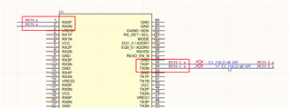
What I would like to do:

Best Regards
Hryhorii
