This thread has been locked.

If you have a related question, please click the "Ask a related question" button in the top right corner. The newly created question will be automatically linked to this question.

THVD1420: RS485 - Glitch(?) and Drop voltage problem.

Part Number: THVD1420
Other Parts Discussed in Thread: TMS320F28388D

Hi there,

I'm dave, beginner hardware engineer.

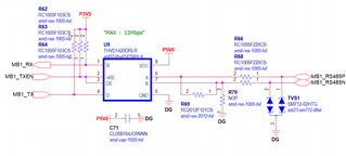
first of all, I designed rs485 schematic as below.

but when I want to communicate with other device (which i dont know schematic.)

I connected power(24v), gnd, rs485_a, rs485_b to other device. (my board supply 24v to other device)

It happen as below pictures.

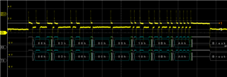
Can i know why glich(?) and it's like drop the voltage level happen like this?

thank you for reply.

  • Hi Dave,

    What pin(s) are you measuring the voltage at in the above oscilloscope shot? 

    Also it does appear as though the TX signal and RX signal are matching - unless I am misreading it - which means the device does seem to be communicating.

    Are you concerned about the overshoot/undershoot of the signal?  This could be caused by parasitic capacitance on the board/cable and due to impedance mismatch - i.e. from board to cable to board at any boundary between these points if the impedance isn't matched energy will be reflected - I assume this is happening at least to a small degree as there are some ripples in the data signal. 

    How long is the cable between two boards - if there is a cable - and what is the characteristic impedance of the traces on the board and if there is a cable its characteristic impedance. I'd imagine there is inherent mismatch due to the series resistor (it would be better to move the series resistors so that the termination is the first "load" seen - as this will be much easier to impedance match and still provides the same benefit. Generally speaking a proper RS-485 system, if configured in a point to point manner which I believe your system is, the other system should be seen as a 120 ohm differential load - if it isn't that it will be very hard to impedance match without more information - but the RS-485 standard uses this as the baseline.

    Please let me know!

    Best,

    Parker Dodson 

  • Thank you for reply.

    anyway, I have one more question. 

    I'm using 3.3v power mcu(TMS320F28388D), That's why i designed 3.3v pull up for R, D(THVD1420DRLR). and vcc is 5.0v for thvd1420drlr(rs485 transiver).

    Is it ok with this design?

  • Hi Dave,

    The transceiver will be fine in that implementation - but I'd be worried about damage to the MCU (unless it has 5V tolerant inputs) as the "R" pin will output close to 5V which if the MCU isn't 5V tolerant could damage the MCU. A level shifter would have to exist from 5V to 3.3V at the R pin - this can be done either discretely or through a level shifting IC. The D, DE, and /RE pins can be pulled to 3.3V as that is >VIH(max) so logic 1's and 0's can still be passed  and since the VCC is 5V the transceiver isn't going to take damage from a 3.3V signal.   

    Please let me know if you have any other questions.

    Best,

    Parker Dodson

  • thank you for your kind reply.