Part Number: DS90UB949-Q1
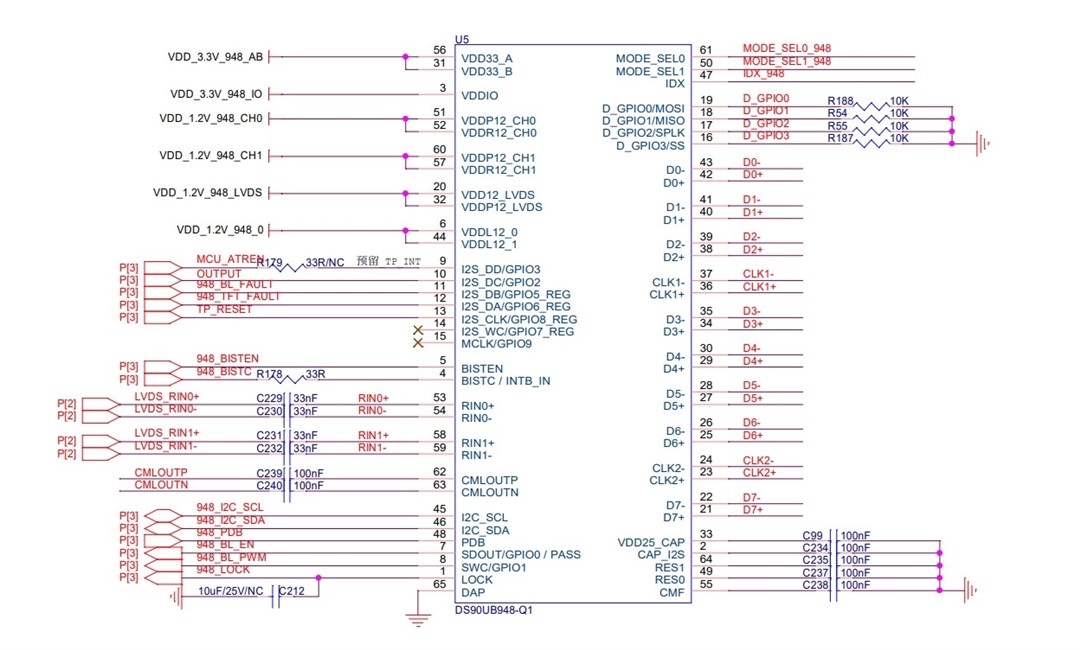
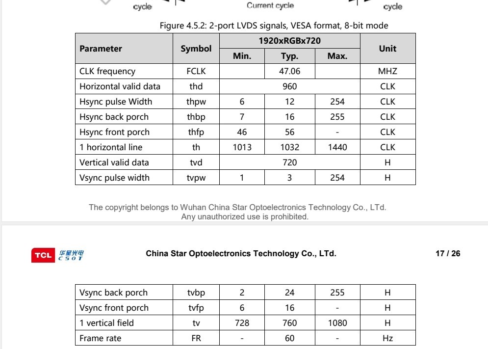
1. The customer uses the DS90UB948 to drive the 1920 * 720 display screen. The external interface of the DS90UB948 is LVDS. This board has been tested and can normally display images from LVDS.
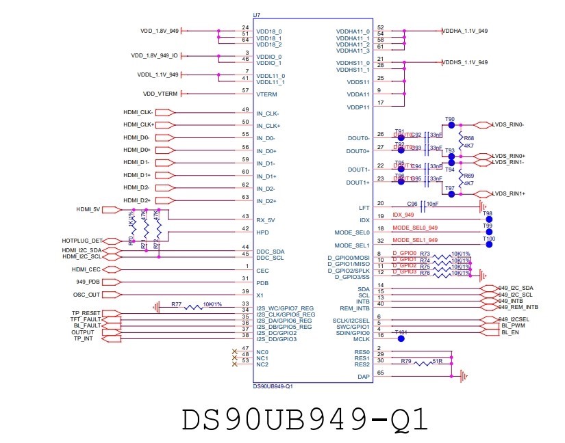
2. In addition, there is a circuit board of DS90UB949, which is connected to the computer through HDMI and to the board of DS90UB948 through LVDS. Now it is necessary to realize the function that the pictures on the computer are transferred to the DS90UB949 through HDMI, and then transferred to the DS90UB948 through LVDS and displayed on the screen.
3. I2C of DS90UB949 is connected to MCU, and DS90UB949 register is configured through MCU.
Now our customers want to know which registers of the DS90UB949 should be configured, and what values should be configured to achieve the following functions?
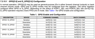
A. The levels of GPIO0, GPIO1 and GPIO8 pins of UB949 are synchronized to GPIO0, GPIO1 and GPIO8 of UB948;
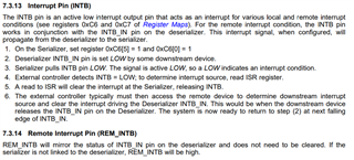
B. The electrical level of INTB pin of UB948 is synchronized to INTB pin of UB949
C. The levels of GPIO6, GPIO5, GPIO3 and GPIO2 pins of UB948 are synchronized to GPIO6, GPIO5, GPIO3 and GPIO2 pins of UB949
