Hello,
We have this device driving an unpowered FPGA and we are trying to figure out the implications.
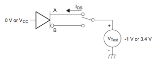
From the datasheet, the drive current is typically 3.4mA across a 100 ohm resistor and short circuit current for one of the output pins (neg or pos) is 4 to 24mA.
In our system, the LVDS output will go through a cable and then forward bias the power clamp diode in the FPGA. Since there is some load, can we assume that the current will remain around 3.4mA, or could the current go higher? Is there a current vs load graph for this part that would show this? How is the 24mA max short current created?
Also, if there is no load will the LVDS output high side be at 3.3V?
Thanks,
Todd