This thread has been locked.
If you have a related question, please click the "Ask a related question" button in the top right corner. The newly created question will be automatically linked to this question.
Hi, Teams!
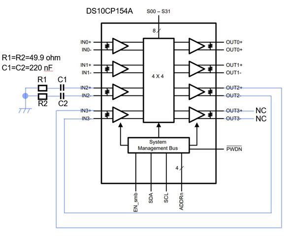
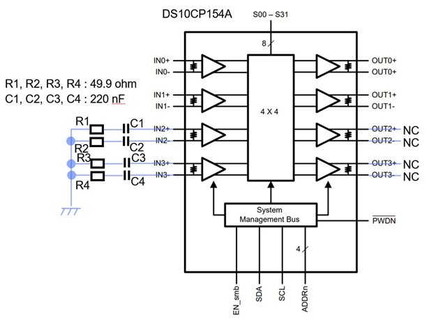
I want to use DS10CP154A for 2x2 LVDS Crosspoint Switch.
I know you have the DS10CP152 for 2x2 LVDS Crosspoint Switch.
But due to procurement issues, I have to use the DS10CP154A.
So please tell me connection of unused input/output ports.
1) What is the recommended connection for the unused LVDS input pins?
2) What is the recommended connection for the unused LVDS output pins?
Best regards,
Tagami
Greetings,
Please AC couple and then 49.9-ohm Resistor to GND on positive and another pair on negative input or outputs.
Regards,Nasser
Dear Nasser,
Thank you for your answer.
But I can't imagine connecting unused pins.
Could you show the connection diagram?
Best regards,
Tagami
Greetings,
From the un-used pin, you would connect to AC coupling Cap(220nF). The other side of the Cap goes to 49.9-ohm Resistor. The other side of this Resistor goes to GND.
Regards,Nasser
Dear Nasser,
Thank you for your reply.
I made a drawing based on your suggestion.
When IN2+/-, IN3+/-, OUT2+/- and OUT3+/- are not used,
is the connection shown in attached figure recommended?
Best regards,
Tagami
Greetings Tagami-San,
Please do not connect IN3 to OUT2. Instead, use Rs and Cs on IN3 to GND - same as what you have on IN2.
Regards,Nasser
Dear Nasser,
Thank you for your reply.
II have modified the schematic.
Are the recommended connections correct in the schematic below?
I have three additional questions.
1) Are C1~C4 required? Please tell me the purpose of placing them.
2) What is the maximum voltage for each of the IN2+, IN2-, IN3+ and IN3− pins?
Required to select resistor and capacitor ratings.
3) Is it acceptable to set R1~R4 to 47Ω? 49.9 ohm is special.
Best regards,
Tagami
Greeting,
1). C1 ~ C4 provide AC impedance.
2). Maximum voltages at these inputs are the common mode voltage - please note data sheet Vcmr parameter(VCC-0.05V).
3). Yes this should be fine.
Regards,Nasser
Dear Nasser,
Thank you for your reply.
I understood Question 1) and 3).
But I want to know about common mode voltage of LVDS inputs.
I believe the Vcmr parameter in the datasheet indicates
an acceptable input common voltage range.
What I want to know this time is the maximum voltage of the IN2+ pin
when connected to GND via C1=220nF and R1=47Ω.
Are they the same voltage?
If the maximum voltage of the IN2+ pin is VCC-0.05=3.25(V),
the power consumption in R1(=47 ohm) will be 0.225W,
requiring a big size resistor.
Is this power consumption correct?
Best regards,
Tagami
Greetings,
Please note common mode voltage noted earlier is provided by the device driving IN2+/- or IN3+/-. There is internal biasing so you would not need to apply any voltage to these pins.
Regards,Nasser
Dear Nasser,
Thank you for your reply.
What is the maximum voltage of the IN2+ pin
when connecting C1 and R1 as shown in the circuit diagram above?
I believe it is equal to the maximum internal bias voltage.
Dear Nasser,
I found Input Current specification of LVDS INPUT (Iin) in the datasheet.
Are the LVDS input current specifications applicable
when connecting C1 and R1 as in the circuit diagram above?
If applicable, the maximum voltage on the IN2+ pin will be 470uV.
Is this calculation correct?
Greetings,
Please note document below. There is internal biasing or failsafe circuit to prevent oscillation(please note section 4.6).
Regards,Nasser
Dear Nasser,
I checked section 4.6 of the LVDS Owner's Manual.
However, I couldn't find any information about the maximum voltage on the input LVDS pins.
Could you tell me the maximum voltage on these input pins?
Required to determine the rating of resistors R1 through R4.
Best regards,
Tagami
Greetings,
Please note since we are AC coupling(note C1 through C4), device uses its own common mode voltage. These Caps isolate us from Appling DC voltage on IN2 and IN3. Therefor we do not need to worry about rating of R1 through R4 somehow damaging the part. We should use 49.9-ohm Resistors just to make sure we have 100-ohm termination across frequency band.
Regards,Nasser