This thread has been locked.

If you have a related question, please click the "Ask a related question" button in the top right corner. The newly created question will be automatically linked to this question.

THVD1450: Recommend part and Review schematic

Part Number: THVD1450
Other Parts Discussed in Thread: THVD1420, THVD1449, , SN65HVD888

Hello Expert,

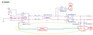
We are testing CS (Conduction Immunity) Certification for EMC Test, there is a problem that the communication was cut off, So we are trying to replace w/ TI product.

1. Do you have any recommend part for passing EMC Test?

2. Question

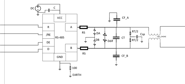
-. In the above circuit, please check how to handle the ground of RS485 IC, TVS, and Thyristor IC.

   In case of TVS and Thyristor IC, is it correct to connect to Earth or connect to GND of RS485 IC?

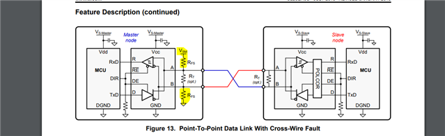
-. Also, if you have an application note that can be referenced, please share it.

Best Regards,

Michael

  • Hi Michael,

    1. We don't have any specific part rated for conducted immunity - this all has to be done externally on our parts. However our parts have been in part of systems that can pass EMC conducted immunity. What  data rate is needed, is a 3.3V supply the only one available or is 5V also an option (we support both - but I just want to see if there are restrictions in part selection), and how many communication nodes need to be supported on one bus?

    2. Protection devices should be referenced to the local ground of the RS-485 device for single ended protection; for differential protection the protection device should be placed between A and B and should be bi-directional. Earth connections - should be connected to ground via a resistor (typically ~100 to 1k to keep loop current low) 

    3. App Note/Reference Design:  High EMC design for absolute encoders: https://www.ti.com/lit/ug/tidudf5/tidudf5.pdf?ts=1678385010171&ref_url=https%253A%252F%252Fwww.google.com%252F 

    It doesn't have to be encoder specific as the EMC protection methods in this design are the general suggestions to start.  Some additional filtering elements may be added to add an additional layer of robustness to the design.

    Please let me know on the performance requirements to see what part would be a good one to work with!

    Best,

    Parker Dodson

  • Hello Parker,

    Thanks for your kind reply.

    1.The supply voltage to replace the competitor is 3.3V to 5V, and other specifications are the same as those of the competitor.

       I checked THVD1449, THVD1420 and need your recommendation.

    2. I don't know well about your mention, could you show a block diagram to make it easier to understand?

        As you know, our customer use differential.

       So, do we have to connect as below?


    Best Regards,

    Michael

  • Hi Michael,

    1. So the THVD1420, THVD1450, and THVD1449 are all decent options in this application:

    1a) The THVD1450 offers the highest IEC ESD protection (+/-18kV), but additional external protection may be required.

    1b) The THVD1420 offers high IEC ESD protection (+/-12kV) and is offered in a small package so good for size conscience applications, but additional external protection may be required

    1c) The THVD1449 offers integrated surge diodes and offers +/-4kV surge and EFT protection - so external protection may not be needed or more cost effective options can be chosen. 

    All of these options are decent choices - the THVD1449 is going to have the most protections on it - but I believe it has a lower rating for IEC ESD protection than the THVD1450.  As a note though - none of these protections are for Conducted immunity specifically so additional circuit elements may be needed.

    2. Protection:

    RS - Series resistor - small value; pulse proof; helps attenuate transient voltage events. Recommended.

    DA and DB - Bidirectional protection diodes that ensure that teh "A" or "B" line w.r.t. ground do not undergo overvoltage events.

    Ddiff - Ensure the differential voltage is clamped to a safe level during a transient event. 

    CT - Termination capacitance - usually 50pF to 100pF - will load bus - used to filter noise from A and B lines.

    RT/2 - Half of recommended termination resistance - so ~60 Ohms to help create a split termination.

    Csp - Split termination capacitor helps filter off high frequency noise .

    CF_A/CF_B - Filter Capacitors for A and B to ground - these will greatly load the bus but can be used to help filter - possible option but has major drawbacks to use.

    CM_CHOKE - a common mode choke to help mitigate common mode noise. 

    Every protection device is referenced to devices local ground - earth connection is connected to local ground through ~100 Ohm resistor to reduce loop currents (and therefore reduce noise)

    For this application I'd recommend everything except CF_A and CF_B (as these have many drawbacks to use) 

    Please let me know if you have any other questions!

    Best,

    Parker Dodson

  • Hi Parker,

    I really appreciated and thanks for your kind explanation.

    It seems to help a lot.

    Best Regards,

    Michael

  • Hi Michael,

    I am glad to help - if you have any follow up questions please let me know!

    Best,

    Parker Dodson

  • Hi Parker,

    Could you also reply to the inquiries below?

    1. In the circuit what you sent, will there be any problems if DC power (sensor power) 24V +, 24V - lines are connected incorrectly to A and B lines?

        Ex) DC 24V + to B, DC 24V - to A

    2. In addition, is there any protection method for 485 A, B lines against wrong wiring?

        I think that I can use a product which has an auto polarity feature. ex, SN65HVD888

        Is it right?

    Best Regards,

    Michael

  • Hi Michael,

    1. So it depends on the diodes used - they will need to be surge rated to handle the power that will need to be shunted. Any higher transient should be mostly mitigated by the pulse proof resistors (R5 in diagram). However it is up to the diodes to handle the clamping in cases of short to power.

    2. So auto-polarity detection would be good for switching the B and A pins around but not other miswirings - other miswirings need to be handled by protection devices on the line. That being said - auto-polarity generally works by having an idle differential bus voltage of >= 200mV - so that if its outputting a 0 when the bus becomes active the device knows that A and B have been switched. This can also be programmed into the controller of the device using the same method but having the controller handle the polarity correction and not the IC. 

    Please let me know if you have any other questions.

    Best,

    Parker Dodson

  • Hi Parker,

    I didn't fully understand about your comment.

    I need your more easier explanation about each item 1, 2. and would like to know your recommended part information about diodes.

    About R5 what you comment, is it typo? It is RS, is it right?

    Best Regards,

    Michael

  • Hi Michael,

    1. I don't have a specific diode recommendation - as it really is going to depend on how much power the power line could potentially delivered. In the past we suggest the CDSOT23-SM712 for protection up to 1kV surges - but if higher protection is needed we don't have a standard diode recommendation. You may need to look at littlefuse or bournes diodes as they are generally more common for higher power surge diodes. 

    But yes - I meant RS not R5 - when I looked at block diagram I made I misread the "S" as a "5" - I apologize for any confusion here. 

    2. Auto-polarity detection parts require external failsafe biasing resistors

    As this sets a default idle bus value for the "R" output. Instructions on how to size these resistors can be found here: https://www.ti.com/lit/an/slyt324/slyt324.pdf

    Polarity correction parts assume that these resistors are there - so if they read a a low value (VA - VB <= -200mV) the device will know that A and B have been swapped and will correct that internally.

    Any RS-485 part can have this feature, as the controller can read the default value and if its a low - then it knows that the polarity is flipped and the controllers firmware will need to invert the DataStream (read 1's as 0's and read 0's as 1's)  

    Auto-polarity doesn't protect from miswiring VCC to A for example but it can correct A being hooked up to a B pin etc...

    Please let me know if you have any other questions!

    Best,

    Parker Dodson