A related question is a question created from another question. When the related question is created, it will be automatically linked to the original question.
If you have a related question, please click the "Ask a related question" button in the top right corner. The newly created question will be automatically linked to this question.
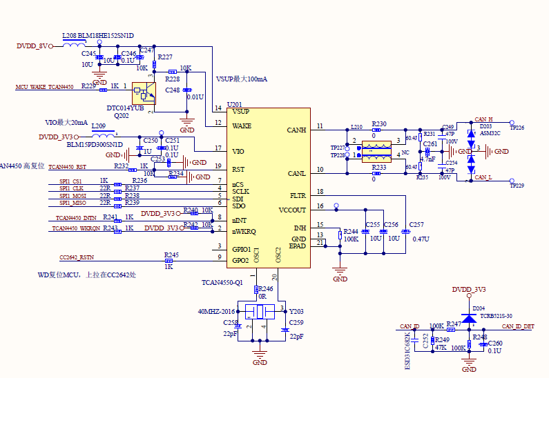
Thanks for posting this! I would recommend ESD2CAN24-Q1 in place of D203.
Depending on your data rate, R231 and R235 might not be needed.
Other than that, assuming you have the correct input/output directions assigned to your nets, I did not find any other points of concern when looking at the schematic.
The TCAN4550-Q1 leaves Sleep mode when a remote wake-up occurs on the CAN bus, when a local wake-up occurs on the WAKE pin, or when there is a power cycle to the device.
If you were making the 24 V system comment in reference to the ESD diode, you could also try the ESD2CAN36-Q1 (36 V instead of 24 V) which is releasing later this year, third quarter.
Ok, just make sure to keep in mind absolute maximum ratings and design best practices. The ESD2CAN36-Q1 might be the best option in the 24 V system.
When the device enters Sleep mode, SPI is off (see Table 8-1). The VCC output is also off. It is expected that in this mode, the entire system is asleep and that the MCU would be off. The only ways to leave Sleep mode are when a remote wake-up occurs on the CAN bus, when a local wake-up occurs on the WAKE pin, or when there is a power cycle to the device.