This thread has been locked.

If you have a related question, please click the "Ask a related question" button in the top right corner. The newly created question will be automatically linked to this question.

TLK10232: Configuration & link questions

Part Number: TLK10232

Hello,

We have used TLK10232 dual phy component for a XAUI to SFP/SFP+ application and I have some questions.

We have found searching in the forum a device initialization for the 10G mode (steps below):

  1. Reset device (write a 1 to 0x1E.0000 bit 15 or assert RESET_N pin)
  2. Make sure the reference clock selection (156.25 MHz or 312.5 MHz) is correct – this is done through register 0x1E.001D bit 12 (default is 156.25 MHz)
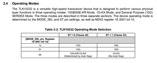
  3. Disable auto-negotiation by writing 1’b0 to 0x07.0000 bit 12
  4. Disable link training by writing 16’h0000 to 0x01.0096
  5. Write 16’h03FF to 0x1E.8020.  This allows the link settings that would normally be configured through KR training to be configured manually instead.
  6. Depending on the link conditions, you may need to change the default configuration of 0x1E.0003 and 0x1E.0004.  For optical connections, we typically recommend changing HS_ENTRACK (0x1E.0004 bit 15) to 1’b1 and HS_EQPRE (0x1E.0004 bits 14:12) to 3’b101.  This can be a starting point, but you may need to do some BER testing to optimize the values.
  7. Issue a data path reset by writing 1’b1 to 0x1E.000E bit 3.

Q1. In order to switch on-the-fly between 1G & 10G modes is it adequate a write in 0x1E.0001 bit 11 followed by data path reset (0x1E.000E bit 3)?

Q2. While the device is in 1G mode how can autonego be activated (1000-BASEX-AN mode)?

Q3. What registers must be be polled for the PHY link to be considered UP? Does it differ between 1G & 10G modes?

Thanks in advance

  • Request noted. We will target to provide our feedback by close of business tomorrow (Friday USA Pacific Time.)

    Rodrigo Natal

    HSSC Applications Team

  • Q1. In order to switch on-the-fly between 1G & 10G modes is it adequate a write in 0x1E.0001 bit 11 followed by data path reset (0x1E.000E bit 3)?

    Q2. While the device is in 1G mode how can autonego be activated (1000-BASEX-AN mode)?

    I'm including datasheet excerpt below for ease of reference:

    When TLK10232 is selected to operate in 10GKR/1G-KX mode (MODE_SEL pin held low), Clause 73 Auto-Negotiation will commence after power up or hardware or software reset. The data path chosen from the result of Auto-Negotiation will be the highest speed of 10G-KR or 1G-KX as advertised in the MDIO ability fields (set to 10G-KR by default). If 10G-KR is chosen, link training will commence immediately following the completion of Auto-Negotiation. Legacy devices that operate in 1G-KX mode and do not support Clause 73 Auto Negotiation will be recognized through the Clause 73 parallel detection mechanism

    In terms of software reset options, there is global reset and data path reset. There is also a register called AN_RESTART. I think the global reset might be too disruptive. I would recommend to try both data path reset and AN_restart options. Some datasheet registers info included below.

    Device Address: 0x1E     Register Address:0x000E     Default:0x0000

    Bit(s)

    Name

    Description

    Access

    15:8

    RESERVED

    For TI use only. Always reads 0.

    RW

    7:4

    RESERVED

    For TI use only. (Default 4'b0000)

    RW


    3


    DATAPATH_RESET (RXG)

    Channel datapath reset control. Required once the desired functional mode is configured.

    0 = Normal operation. (Default 1’b0)

    1 = Resets channel logic excluding MDIO registers. (Resets both Tx and Rx datapath)


    RW SC(1)


    2


    TXFIFO_RESET (G)

    Transmit FIFO reset control. Applicable in 10G mode only. Not required in 10GKR mode as 10GKR FIFO is self centering.

    0 = Normal operation. (Default 1’b0)

    1 = Resets transmit datapath FIFO.


    1


    RXFIFO_RESET (G)

    Receive FIFO reset control. Applicable in 10G mode only. Not required in 10GKR mode as 10GKR FIFO is self centering.

    0 = Normal operation. (Default 1’b0)

    1 = Resets receive datapath FIFO.

    0

    RESERVED

    For TI use only. (Default 1'b0)

    RW

    Device Address: 0x07     Register Address: 0x0000     Default: 0x3000

    Bit(s)

    Name

    Description

    Access

    15

    AN_RESET (RX)

    1 = Resets Auto Negotiation

    0 = Normal operation (Default 1’b0)

    RW/SC

    14

    RESERVED

    For TI use only. Always reads 0.

    RW

    13

    RESERVED

    For TI use only (Default 1’b1)

    RW

    12

    AN_ENABLE (RX)

    1 = Enable Auto Negotiation (Default 1’b1) 0 = Disable Auto Negotiation

    RW

    11:10

    RESERVED

    For TI use only. Always reads 0.

    RW

    9

    AN_RESTART (RX)

    1 = Restart Auto Negotiation

    0 = Normal operation (Default 1’b0)

    If set, a read of this register is required to clear AN_RESTART bit.

    RW/SC(1)

    8:0

    RESERVED

    For TI use only. Always reads 0.

    RW


    Q3. What registers must be be polled for the PHY link to be considered UP? Does it differ between 1G & 10G modes?

    The PMA status registers, which apply to both 10G and 1G. See below from datasheet.

    Table 8-58. PMA_STATUS_1

    Device Address: 0x01     Register Address:0x0001     Default: 0x0002


    Name

    Description

    Access


    FAULT (RX)

    1 = Fault condition detected on either Tx or Rx side 0 = No fault condition detected

    This bit is cleared after Register 01.0008 is read and no fault condition occurs after 01.0008 is read.

    RO


    RX_LINK (RX)

    1 = Receive link is up

    0 = Receive link is down

    RO/LL


    Device Address: 0x01     Register Address:0x0001     Default: 0x0002


    Bit(s)

    Name

    Description

    Access

    1

    LOW_POWER_ABILITY (RX)

    Always reads 1.

    1 = Supports low power mode

    0 = Does not support low power mode

    RO

    Table 8-65. PMA_STATUS_2

    Device Address: 0x01     Register Address: 0x0008     Default: 0xB000

    Bit(s)

    Name

    Description

    Access


    15:14


    DEV_PRESENT (RX)

    Always reads 2’b10

    0x = No device responding at this address

    10 = Device responding at this address

    11 = No device responding at this address


    RO


    13

    TX_FAULT_ABILITY (RX)

    Always reads 1’b1.

    1 = Able to detect fault condition on Tx path

    0 = Not able to detect fault condition on Tx path


    RO


    12

    RX_FAULT_ABILITY (RX)

    Always reads 1’b1.

    1 = Able to detect fault condition on Rx path

    0 = Not able to detect fault condition on Rx path


    RO

    11

    TX_FAULT (RX)

    1 = Fault condition detected on transmit path

    0 = No fault condition detected on transmit path

    RO/LH

    10

    RX_FAULT (RX)

    1 = Fault condition detected on receive path

    0 = No fault condition detected on receive path

    RO/LH


    8

    TX_DISABLE_ABILITY (RX)

    Always reads 1’b0.

    1 = Able to perform transmit disable function

    0 = Not able to perform transmit disable function


    RO

    Regards,

    Rodrigo Natal

  • Thanks Rodrigo for your answers.

    Regarding the Q1 & Q2 let me clarify the desired operation of our product:

    The modes of the PHY that it will operate are:

    1. 1G without auto-negotiation (defined by 0x1E.0001 bit 11=0 & 0x07.0000 bit12=0 & 1E.0001 bit 10=0)
    2. 10G without auto-negotiation (defined by 0x1E.0001 bit 11=1 & 0x07.0000 bit12=0 & 1E.0001 bit 10=0)
    3. 1G with auto-negotiation (defined by 0x07.0000 bit 12=1 & 0x07.0011 bit 7=0 & 0x07.0011 bit 5=0)

    The objective of mode 3 is to have auto-negotiation enabled but with only 1G capability possible.

    So are the register settings described above correct?

    Thanks in advance. 


  • Below datasheet snapshot captures the operating mode selection details. The auto-neg option supported is dual 1G/10G.

    Thanks,

    Rodrigo Natal