This thread has been locked.

If you have a related question, please click the "Ask a related question" button in the top right corner. The newly created question will be automatically linked to this question.

DP83869HM: SGMII signal integrity

Part Number: DP83869HM

Hello TI-Members,

I have the following setup (1x DP83869HM in bridge-mode, 1x DP83869HM in SGMII-to-Copper mode):


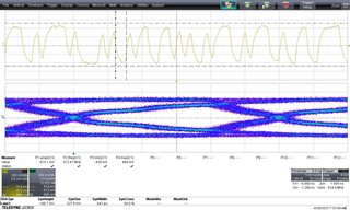
I measured signal integrity (with a 5 GHz differential probe and 6 GHz scope) at the input of SGMII-to-Copper PHY (after AC-caps):


These are my results:
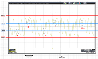

My questions are:
- How to know, if e.g. sample position "B" is a period of 1-1-1 or if this is a period of 1-0-1 but the zero voltage level is not reached.
- What is the SGMII input voltage treshold specification? I can't find this spec in the datasheet
- In the DS the SGMII output is specified with Output Differential Voltage = 1060 (min) / 1100 (typ) / 1140 (max)
--- At the receiver the SGMII-signal is only between -400mV to 400 mV (800mV)
------ Does it mean that I have significant losses on the transmission lines?

Thx in advance!
Julian

  • Hi Julia,

    Can I ask couple question for further debug:

    • Are you receiving different data than you expected in SGMII communication? Are you able to receive any data through SGMII communication?
    • Are you able to check register 0x0037 3 times to see rather SGMII is auto negotiation complete
    • Are you able to generate an eye diagram for the SGMII communication?

    --

    Thank you,

    Hillman Lin

  • HEy Lin,

    sorry for my late response! I measured eye diagrams now, for RX and TX-side.

    Please see attachments...


    RX-side (after AC-caps of SGMII-to-Copper PHY; left side of the above picture) with iperf running:


    TX-side (after AC-caps of RGMII-to-SGMII bridge PHY; right side of the above picture) with iperf running:

    !

    Would be great to get a feedback about the signal integrity and if this diagrams lead to a solid interfacing between the two PHYs.

    Thx in advance!

  • Hi Julian,

    For further clarification on your PHY issue, I would like to clarify on this:

    • Are you receiving different data than you expected in SGMII communication? Are you able to receive any data through SGMII communication?
    • Did you see a link up on your SGMII communication interface? 
      • Are you able to check register 0x0037 3 times to see rather SGMII is auto negotiation complete
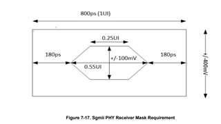
    •  Could you compare the eye diagram mask requirement which is shown below:

    --

    Thank you,

    Hillman Lin

  • Hi and thx again,

    1) Data is received. The overall link (MAC<=>PHY1<=>PHY2<=>PC) reaches about 920Mbit/s but sometimes with a lot of retries/dropped packages in TCP/IP mode.
    2) Link is up and stable
    3) Auto negotiation is disabled for SGMII, because SGMII always runs with 125 MHz. With auto negotiation enabled, there is no link between the PHYs.
    4) I will provide a feedback later this week.

  • Here now some eye-diagram information, see picture:

    On the bottom red box of the picture, some measurement data from the scope is also shown.

    Sorry, I'm not very familiar with eye-diagrams, so please help me to interpret my measurements. 

    Thanks in advance!
    Julian

  • Hi Julian,

    Here is the specification on how to read the SGMII PHY receiver Mask Requirement:


    The amplitude or peak to peak between the signal should be greater than +/- 100mV. However, from the eye diagrams you send me, I see that your peak to peak only goes up to +/- 90mV. Are you able to increase the output driver level on the MAC side?

    --

    Regards,

    Hillman Lin

  • Hi again,

    First of all, my notes on the eye diagram were wrong, it is +-180mV, not +-90mV:

    The MAC is integrated in an AM64x-SoC from TI.

    How should it help to increase the output driver level on MAC side, when I have issues between the two PHYs in SGMII-mode?

    And if this really helps, how to do this with the Sitara AM64x? Is there any configuration I can adjust?

  • Hi Julian,

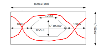
    Are you able to scale the mask that I provided earlier and import it or paste it into your SGMII eye diagram. Make sure the scale is 800ps for X-axis and +/-400mV on Y-axis.

    Refer to the following plot:

    --

    Thank you,

    Hillman Lin

  • Hi,

    I don't get why you want me to do this. All required information is in the already posted picture.

    Eye-Height=+/- 180mV
    Eye-Width=677ps


    Also, unfortunately you have never really answered my questions:

    - What is the SGMII input voltage treshold specification? I can't find this spec in the datasheet

    - How should it help to increase the output driver level on MAC side, when I have issues between the two PHYs in SGMII-mode?

    Thx in advance!

  • Hi,

    two more questions:
    1) Is it possible to increase the output driver level of the DP83869HM by MDIO-register settings?
    2) Is it correct that the AC-caps are placed on the receiving side or should they always placed on the sending side?

    Thanks in advance!

  • Hi Julian,

    We shared the input requirements of Sgmii in the form of mask in this thread. In the mask you can see that 100mV is also ok for the PHY (if other mask criteria is also met : rise/fall time, jitter). If signal swing at input is meeting the mask we don't expect any data transmission issues. We dont have any further information that we can share. Are you seeing any packet errors?

    --

    Regards,

    Hillman

  • Hey again,

    Thanks for your reply!

    can you please answer the following questions:

    What is the SGMII input voltage treshold specification? I can't find this spec in the datashee
    1) Is it possible to increase the output driver level of the DP83869HM by MDIO-register settings?
    2) Is it correct that the AC-caps are placed on the receiving side or should they always placed on the sending side?
  • Hi Julian,

    I would like to take one step back. Could you check if you are seeing any packets loss or packets error in your SGMII communication when you observe a SGMII integrity? Are you able to perform a SGMII communication even with the signal integrity?

    • Please do follow the mask requirement I send you earlier for SGMII signal specification
    • Could you check if you are seeing any packets loss in your system before we move on to the output driver level?
    • AC caps should place on the output side of the PHY.

    --

    Regards,

    Hillman Lin

  • Hi again,

    Please do follow the mask requirement I send you earlier for SGMII signal specification

    I did this. I'm in spec, but quite close regarding eye-opening for 0.25UI, as shown in my diagrams.

    Could you check if you are seeing any packets loss in your system before we move on to the output driver level?

    Please see my previous post above => 
    1) Data is received. The overall link (MAC<=>PHY1<=>PHY2<=>PC) reaches about 920Mbit/s but sometimes with a lot of retries/dropped packages in TCP/IP mode.
    2) Link is up and stable

    AC caps should place on the output side of the PHY.

    Thx! Then, this is wrong on my board. I will try the other direction.

  • Hi Julian,

    Sorry for missing your information on the earlier post regarding to the packages drop.

    For the next steps for debug, are you able to do a MII loopback on PHY2 and check the package on the MAC side to see any package drop? The detail information will be on 9.3.4 in the datasheet or register 0x0000

    Could you also provide a schematic for further debug?

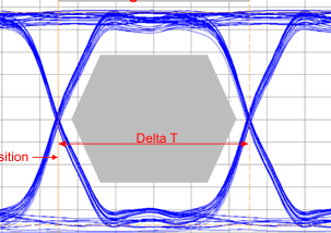
    The reason why I was concerning on the mask requirement is the circle region which is shown below:

    --

    Regards,

    Hillman Lin

  • HI,

    For the next steps for debug, are you able to do a MII loopback on PHY2 and check the package on the MAC side to see any package drop? The detail information will be on 9.3.4 in the datasheet or register 0x0000

    This will take some time.

    Could you also provide a schematic for further debug?

    Attached

    The reason why I was concerning on the mask requirement is the circle region which is shown below:

    Same here.

    PHY1_RGMII.pdfPHY2_SGMII.pdf

  • Hi Julian,

    Regarding to the MII loopback, let me know if you are having trouble on it.

    Meanwhile, we will go over your schematic and provide you a response as soon as possible.

    --

    Regards,

    Hillman Lin

  • Hi Julian,

    Other than changing AC capacitors on SOP and SON, I did not see any other issue on the SGMII side schematic.

    --

    Regards,

    Hillman Lin

  • For the next steps for debug, are you able to do a MII loopback on PHY2 and check the package on the MAC side to see any package drop? The detail information will be on 9.3.4 in the datasheet or register 0x0000

    I now checked what information this test is giving. I don't see value in this, MII loopback is for 100Mbit and it only tests the communication between MAC and first PHY. We have two PHYs with RGMII (MAC<->PHY1) and SGMII (PHY1<->PHY2). I don't see any issues between MAC and PHY1, the track length is very short and all rules where applied regarding PCB design. I see issues in SGMII transmission. So why you want me to do that?

  • Hi Julian,

    Hillman is out of office today, I will reply on his behalf. 

    From reading the above, I am seeing that data communication is happening fine and the SGMII signal integrity looks great. What is the concern?

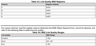
    We can check for receive errors in the PHY (register 0x15) and check the MSE to see the cable side signal quality, using the following procedure. 

    Thanks,

    David