This thread has been locked.

If you have a related question, please click the "Ask a related question" button in the top right corner. The newly created question will be automatically linked to this question.

TUSB214-Q1: Please review the schematic, and have some question.

Part Number: TUSB214-Q1
Other Parts Discussed in Thread: TUSB214, TUSB216

Hello TI experts,

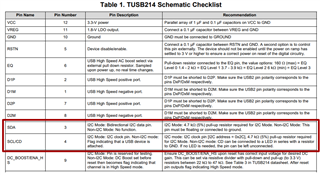
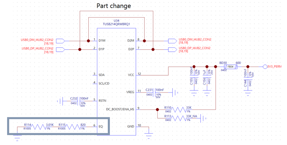
my customer tests TUSB214-Q1 in their product. Could you review the schematic first?

and here are some questions ;

1. they tested resistors in EQ pin for 0 ohm and 3.821K, but they cannot found any differences.

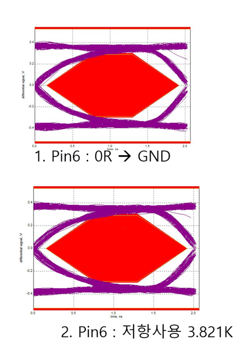
Could you check the possible reason?

2. TUSB214-Q1 can control AC boost and DC boost both using external resistor and I2C controlled register.

the customer wants to control using external resistor. should I do something for it? now they just left floating SCL and SDA pin.

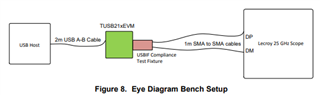
3. they tested TUSB214-Q1 using teflon wire which length is about 100mm. does it affect to the performance of TUSB214?

Please check this issue. Thanks.

Best regards,

Chase

  • Hi Chase,

    Schematic looks good.

    1. Please double-check that the test fixture is connected to TUSB214-Q1 before enable the source to send the TEST_PACKET. You can refer to the test procedure from the app note (High Speed Signal Quality Test Modes - SLLA593). It might be helpful to see testing section on this app note (TUSB2XX Implementation Guide - SLLA392)

    2. In non I2C mode, the SDA pin must be floating or connected to ground. Please see below TUSB214 schematic checklist.

    3. Are you asking the wire is pre-channel or post-channel? Please refer to below eye diagram bench setup for the length. 

    Best,

    Josh

  • Dear Josh,

    Thank you for your support.

    for the answer 3, They use teflon wire instead of 2m USB A-B cable.

    and Should we use sma to sma cable to check eye diagram?

    Best regards,

    Chase

  • Hi Chase,

    Teflon wire for pre-channel is feasible instead of USB A-B cable, but we recommend to use SMA cable between USB IF text fixture and oscilloscope for checking the signal integrity and eye diagram.

    Please let me know if you have any further questions.

    Best,

    Josh

  • Dear Josh,

    Thank you for your support.

    My customer still cannot check the effect of TUSB214.

    Can you guess the reason of not working? What can we do for the next step?

    Best regards,

    Chase

  • Dear Josh,

    Please let me know if there are any updates about the issue above. Thanks.

    Best regards,

    Chase

  • Hi Chase,

    I apologize I didn't know your question was posted and missed the response.

    Please below the comments of the following customer's question from another thread. Note that it would be appreciated if you could tell the customer to ask any questions on this thread to track the issue.

    TUSB214 failed to check operation. --> I want a quick answer

    --> ECU to TUSB214 : USB Eye-Pattern test ==> Signal No Change..

    Removed Tusb216 from Tusb216 board and used TUSB214 (use TUSB214 VCC: 3.3V)

    If the customer followed the test fixture procedure, now we can approach the device internally. Since the eye diagram shows no change even boost level changed, it means the device is not working properly. As the customer said that they placed TUSB214-Q1 on TUSB216 EVM, I would ask if the customer checked the pin compatibility. Note that their operation is not 100% identical. Please refer to this thread regarding the compatibility. Let me know if you have any further questions.

    Best,

    Josh

  • Dear Josh,

    Thank you for your support.

    I checked with my customer yesterday, and we confirmed DC boost and AC boost anyway.

    here is my additional question;

    in the process of test, we should followed the steps below.

    1. check usb communication disabled. (no data on D+ and D-)

    1. apply 3.3V to TUSB214. (including reset)

    2. enable usb communication.

    if we apply 3.3V after USB communication is started, TUSB214 does now work at all. Is it right process?

    I am asking it because TUSB216 does not affect the sequence. (applying VDD first or enable USB communication, do not matter.)

    Best regards,

    Chase

  • Hi Chase,

    As you mentioned above, the steps are only allowed to check the performance.

    1. Check USB communication disabled.
    2. Apply Vdd.
    3. Send Test_Packet pattern via text fixture.

    Best,

    Josh