This thread has been locked.

If you have a related question, please click the "Ask a related question" button in the top right corner. The newly created question will be automatically linked to this question.

DS26C31T: outputs are damaged

Part Number: DS26C31T
Other Parts Discussed in Thread: STRIKE

Hello,

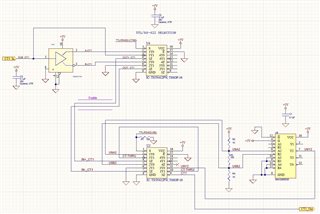
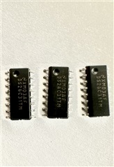
I use the DS26C31TM driver and the MAX3095ESE receiver. Both are powered by 5V.

I have a resistor network at the receiver input (1K + 100 + 1K), as recommended by the datasheet.

In between the driver and receiver signals I have TS5N412PW analog switches, to select TTL or RS-422 signaling.

I notice that several of the driver outputs are getting damaged when I select the RS-422 path. I do not know why.

Regards,

Victor

 RS422 path.SchDoc

  • Hi Victor,

    Do you have a scope shot from the driver output that you could share, it would very helpful if I could see normally and during a switch)

    Could you also describe the damage you are seeing - i.e. are both pins damaged, if not which one; are the pins stuck in a specific state (pulled up or pulled down and won't change) or are they stuck high "Z" ? 

    Also does the damage occur at the switching event (i.e. when you switch the bus) or does the bus work for a bit after the switch and then fail? 

    The schematic itself looks okay - you usually don't see analog switches on the differential bus - but the concern is actually usually with the switch itself or the signal quality of the system - which wouldn't explain driver damage - so it most likely is due to a transient in the system is my guess. These switches do not spec charge injection - the switch will produce a charge injection event during the switch - which will cause a deviation in the VOUT voltage - this may not be enough to break the driver - but this driver isn't really protected below 0V - so a negative transient could damage the device (RS-422 only requires receivers to have a +/-7V common mode input range - which gives protection - drivers do not have this requirement in RS-422 devices - so they are less robust) 

    Please let me know on the questions above so I can dig a little deeper into the issue for you!

    Best,

    Parker Dodson

  • Hi Parker,

    Thanks for the reply!

    In most cases it is the non-inverting output that gets damaged. it gets stuck at the Low state, or it still transitions, but the voltage level is very low (less than 1V). I do not have scope shots but can obtain them.

    The damage occurs after I plug the receiver in. the switch on the driver side is steady, configured for a differential output. The receiver circuit gets powered up and then configured for a differential input. I do not have a precise knowledge as to when exactly the damage occurs. I guess I can try to reproduce the damage, adding wires to probe at several points.

    My guess is also with the switches being the culprit, but I'm not clear. We do need to be able to select between a TTL and/or RS422 output. should I look into using SSRs?

    Perhaps I should put surge suppressors on the driver outputs?

    Thanks,

    Victor

  • Hi Victor,

    Thank you for the reply! When you are able to get the scope shots please share them - also if possible could you take a picture of the top side of a failing device so I can look at the part marking to trace it in our systems to see if there is anything concerning there as well that would be great.

    With that being said the information you have provided does seem to match with some type of electrical overstress damage on the non-inverting pin - as it seems there is a low impedance path to ground on the RS-422 driver pin. Failure at connection of the receiver seems like it could be some transient is produced at the time of connection - at least that seems like it would be the most likely culprit as this is the time period when a transient would be most likely. The switches really should basically just be an RC on the line - and based on its spec's I am not sure if its the culprit by itself or it could be in conjunction with entire system (it has a low flat Ron (~3 Ohms) with low capacitance due to using a single FET + charge pump architecture - so unless you have a very long bus the additional switch capacitance shouldn't usually be an issue)   - how long is the bus - I am assuming its probably not super long - but I'd like to verify that as well. 

    I don't think SSR's will be necessary - they usually are more expensive and I am not 100% sold on the switch being the intrinsic problem - while not super common - I don't really see from a specification point of view that these parts will be of issue- most likely they would break if there was an issue with the switches on the bus.

    However you do bring up my next point - protection on the driver outputs is probably a good idea. If it is just a transient when the receiver is connected or shortly afterwards it could be suppressed  with protection diodes. I'd also add a ~10 Ohm pulse proof resistor on each of the driver outputs if you are going to add protection diodes - I don't have a specific diode to recommend as my general go-to is actually an RS-485 diode and won't clamp at the appropriate levels - but clamping at ~5.5V would be a good point to start with as the driver really isn't going to output that high of a value (so normal operation is mostly unimpeded - some additional capacitance - but once again unless you are working with a long bus (relative to data-rate ) or have strict capacitance per communication node requirements  it really shouldn't be that much of a concern.  The only thing is when picking the diode is that you need to be sure that it can appropriately handle the power that will be dumped into it - and I doubt you would need something more robust than a TVS from what I think is the most likely culprit - but if the transient is relatively longer lasting you may need a slightly more robust type of protection diode. 

    So please when you have the scope shots if you could share them as well as a picture of the top markings of the one of the failing units please share them so I can get a better idea of if this is just an applications issue that can be solved with some additional driver protection.

    If you also have any other questions in the mean-time please do not hesitate to ask!

    Best,

    Parker Dodson

  • Thanks Parker!

    I'll look into the ESD protection.

    I'll also try to get scope shots for you. in the meantime, here is a photo of the damaged parts.

    Regards,

    Victor

  • here are some scope shots.

  • Hi Victor,

    Thanks for the additional information!

    I am having some trouble with my part marking lookup tool at the moment - but as soon as I am able to get the request through I will update you with more. 

    So is this scope shot from the damaged device? If so - yeah it definitely seems as if one the pins has a low impedance path to GND which is causing this. Once again - this is cause most likely by electrical overstress.

    Do you have a scope shot of a working system at the time when the receiver is plugged in - I am thinking the even may occur on multiple boards - but may not happen every time. It could also the be the result of an ESD strike when the receiver is connected - which would line up with EOS damage as well. 

    Will you be able to test the system again with protection diodes - as from everything I have seen I do think the issue is that there is a possible transient or ESD strike that may occur on the line - especially with the low fail rate - I think protection diodes most likely are the go to solution for this type of problem. I will update when the part marking lookup tool that we have internally is working for me again if there is any issue there - but this isn't the most likely issue.

    Best,

    Parker Dodson

  • Hi Victor,

    So unfortunately - I think you may have counterfeit devices. These parts do not show up in our internal system that I am able to access. So the next steps is to go to our anti-counterfeit page as I don't think this is an applications issue. 

    Please see link here: https://www.ti.com/support-quality/quality-policies-procedures/anti-counterfeit.html for next steps and information about our anti-counterfeit program. 

    Best,

    Parker Dodson

  • Hi Parker! I just saw this message. WOW!! That could explain the problem? 

    Should I not be concerned of having this issue with a real TI Part?

    Perhaps I should look to put a protection device anyway?

    Thanks,

    Victor

  • Hi Victor,

    Yes it could explain the problem - unfortunately that does seem to be the trend with counterfeits - nothing in particular about the application seems concerning, yet the driver outputs suffer damage. 

    In general - I am not too concerned with real TI parts for this application - however protection diodes are extremely common in these types of applications and I see them more often than not. So to increase the robustness of the sub-system, protection diodes are a good idea to implement, but not strictly necessary (it will really depend on application how necessary they are).

    Please let me know if you have any other questions!

    Best,

    Parker Dodson