This thread has been locked.

If you have a related question, please click the "Ask a related question" button in the top right corner. The newly created question will be automatically linked to this question.

DS250DF410: DS100DF410 retimer register configuration values for 10G single Lane XFI interface

Part Number: DS250DF410
Other Parts Discussed in Thread: DS100DF410

Hi Team,

We are designing a 10G link between two separate boards. Board 1 has Marvell's cavium processor CN8350 SOC and Board2 has TI-6638K2k SOC. The 10G link is implemented over xfi interface. It uses single differential pair for 10.3125 speed. Both the board are connected together using midplane via edge finger connector.

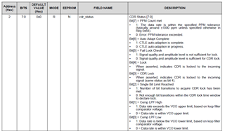
A retimer IC  DS100DF410 is connected at the Rx line of each board. We tried to figure out the configuration sequence of the retimer. Which I am attaching in this mail thread. Kindly verify whether this register sequence is correct.

We are able to detect the eth interface at both the SOC. But we are not able to send and receive any data over the lines.  We are doubtful about the correct retimer register sequence.

Kindly suggest other methods, if any,  to debug the link.  please clarify what values we should keep to bring up a XFI interface supporting 10G link speed.

default-sequence.txt
Fullscreen
1
2
3
4
5
6
7
8
9
10
11
12
13
14
15
16
17
18
19
0x0 Shared Registers_0x00 00
0x1 Shared Registers_0x01 70
0x2 Shared Registers_0x02 00
0x3 Shared Registers_0x03 00
0x4 Shared Registers_0x04 01
0x5 Shared Registers_0x05 10
0x6 Shared Registers_0x06 00
0x7 Shared Registers_0x07 05
0xFF Global Registers_0xFF 04
0x0 Channel 0_0x00 00
0x1 Channel 0_0x01 00
0x2 Channel 0_0x02 00
0x3 Channel 0_0x03 00
0x4 Channel 0_0x04 00
0x5 Channel 0_0x05 00
0x6 Channel 0_0x06 00
0x7 Channel 0_0x07 00
0x8 Channel 0_0x08 00
0x9 Channel 0_0x09 00
XXXXXXXXXXXXXXXXXXXXXXXXXXXXXXXXXXXXXXXXXXXXXXXXXX

  • Hi Megha,

    The DS100DF410 programming guide outlines the correct register sequences for some common device configurations:

    https://www.ti.com/lit/an/snla323/snla323.pdf

    Please try the configuration sequence in Table 9.

    Thank you,

    Evan

  • In addition to Evan's configuration instructions, see below debug suggestions.

    • Make sure that auto-negotiation and link training are disabled on your SOCs at both ends of the link
    • Do confirm that the retimer is achieving CDR lock as part of your system link bring-up. You may check the retimer CDR status via channel register 0x02

    Regards,

    Rodrigo Natal

  • Hi Evan, rodrigo,

    I checked the configuration at our end and then configured the register sequence as per the snla323.pdf [table 9] document. I checked the 0x2f for CDR lock status. It's not locking the CDR. Autonegotiation is disabled at our end and link training is also disabled at our end.

    Please find the i2cdump of retimer device. Please suggest the values.

    -------board1--------CN8350 cavium processor---------

    This board has 3 10G xfi links connected to 3 board2.


    root@debian_on_OCTEON-TX:/home# i2cdump -f -y 0 0x1a

    No size specified (using byte-data access)
         0  1  2  3  4  5  6  7  8  9  a  b  c  d  e  f    0123456789abcdef
    00: 00 00 00 00 00 00 00 00 00 00 10 0f 08 00 93 69    ..........???.?i
    10: 3a 20 a0 30 00 10 7a 36 40 23 00 03 24 00 e1 55    : ?0.?z6@#.?$.?U
    20: 00 00 00 40 40 00 00 00 00 00 30 00 72 80 00 c6    ...@@.....0.r?.?
    30: 00 20 11 88 bf 1f 31 00 00 00 00 00 00 00 80 00    . ????1.......?.
    40: 00 01 04 10 40 08 02 80 03 0c 30 41 50 c0 60 90    .???@?????0AP?`?
    50: 88 82 a0 46 52 8c b0 c8 57 5d 69 75 d5 99 96 a5    ???FR???W]iu????
    60: 00 00 00 00 00 00 00 20 00 0a 44 00 00 00 00 00    ....... .?D.....
    70: 03 20 00 00 00 00 b0 c8 57 5d 69 75 d5 99 96 a5    ? ....??W]iu????
    80: 00 01 04 10 40 08 02 80 03 0c 30 41 50 c0 60 90    .???@?????0AP?`?
    90: 88 82 a0 46 52 8c b0 c8 57 5d 69 75 d5 99 96 a5    ???FR???W]iu????
    a0: 00 01 04 10 40 08 02 80 03 0c 30 41 50 c0 60 90    .???@?????0AP?`?
    b0: 88 82 a0 46 52 8c b0 c8 57 5d 69 75 d5 99 96 a5    ???FR???W]iu????
    c0: 00 01 04 10 40 08 02 80 03 0c 30 41 50 c0 60 90    .???@?????0AP?`?
    d0: 88 82 a0 46 52 8c b0 c8 57 5d 69 75 d5 99 96 a5    ???FR???W]iu????
    e0: 00 01 04 10 40 08 02 80 03 0c 30 41 50 c0 60 90    .???@?????0AP?`?
    f0: 88 82 a0 46 52 8c b0 c8 57 5d 69 75 d5 99 96 a5    ???FR???W]iu????

    -------board2--------TI-SOC----------

         0  1  2  3  4  5  6  7  8  9  a  b  c  d  e  f    0123456789abcdef
    00: 00 10 dc 00 00 00 00 00 00 00 10 0f 08 00 93 69    .??.......???.?i
    10: 3a 20 a0 30 00 10 7a 36 40 23 00 03 24 00 e1 55    : ?0.?z6@#.?$.?U
    20: 00 00 00 40 00 00 00 21 38 20 30 00 72 80 00 c6    ...@...!8 0.r?.?
    30: 00 20 11 88 bf 1f 31 00 10 00 00 00 00 00 80 00    . ????1.?.....?.
    40: 00 01 04 10 40 08 02 80 03 0c 30 41 50 c0 60 90    .???@?????0AP?`?
    50: 88 82 a0 46 52 8c b0 c8 57 5d 69 75 d5 99 96 a5    ???FR???W]iu????
    60: 00 00 00 00 00 00 00 20 00 0a 44 00 00 00 00 00    ....... .?D.....
    70: 03 20 00 00 00 00 b0 c8 57 5d 69 75 d5 99 96 a5    ? ....??W]iu????
    80: 00 01 04 10 40 08 02 80 03 0c 30 41 50 c0 60 90    .???@?????0AP?`?
    90: 88 82 a0 46 52 8c b0 c8 57 5d 69 75 d5 99 96 a5    ???FR???W]iu????
    a0: 00 01 04 10 40 08 02 80 03 0c 30 41 50 c0 60 90    .???@?????0AP?`?
    b0: 88 82 a0 46 52 8c b0 c8 57 5d 69 75 d5 99 96 a5    ???FR???W]iu????
    c0: 00 01 04 10 40 08 02 80 03 0c 30 41 50 c0 60 90    .???@?????0AP?`?
    d0: 88 82 a0 46 52 8c b0 c8 57 5d 69 75 d5 99 96 a5    ???FR???W]iu????
    e0: 00 01 04 10 40 08 02 80 03 0c 30 41 50 c0 60 90    .???@?????0AP?`?
    f0: 88 82 a0 46 52 8c b0 c8 57 5d 69 75 d5 99 96 a5    ???FR???W]iu????

  • Hi Megha,

    Could you share a block diagram of the system?

    Board 2 register dump shows CDR locked (0x2[3]) with valid eye measurements (0x27, 0x28).

    Board 1 register values indicate CDR is not locked, with ppm tolerance exceeded and single bit check limit not passed.

    Please confirm the TX signal characteristics for board 1 into the retimer (data rate, pattern, amplitude, de-emphasis settings, ...).

    Also, please try disabling single bit limit check (0xC[3] = 0) to see if this affects CDR lock for board 1.

    Thank you,

    Evan