


1. Connection mode confirmation of CSI-MIPI for 1-Lane and 2-Lane:
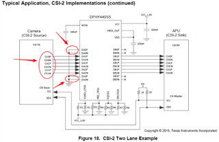
As per the reference design in the specification, 2-Lane uses data 1/2 channel and data 0/3 channel is grounded. What I want to confirm is that the CSI-MIPI design of 2-Lane must strictly follow the reference design? How to design the CSI-MIPI connection of 1-Lane?
2. About the Dynamic De-skew function
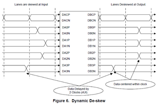
As described in the specification, the output pin automatically compensates for inconsistent offsets between the clock and data received at the device input port. Can this compensation be set externally to either set not to adjust or to change the degree of adjustment?
3. The design problems we encountered on the project
a. Application hardware block diagram
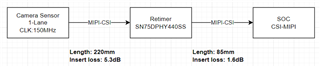
b. Specific problem description
i. When Retimer is not used, there will be some substandard items in the MIPI eye diagram measurement at SOC end. The specific eye diagram is as follows:
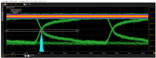
ii. When using Retimer, it can pass the eye diagram measurement normally. The specific eye diagram is as follows:

iii. It can be seen from the above two control graphs that the quality of eye image signal can be improved after adding Retimer. However, another problem will be caused: after adding Retimer, after the Camera works normally for a period of time, an error message of CSI-MIPI PHY will appear on the SOC side. The specific error message is as follows: CAM_ERR: CAM-ISP: cam_ife_csid_irq: 4922 CSID:3 UNBOUNDED_FRAME.
In the same case, without Retimer, although the signal quality will be relatively poor, the same error will not occur.At present, the initial suspicion is that the Dynamic De-skew function may be causing the problem, but there is no proper means to locate it. For the above problems, I hope to help provide positioning and solving ideas and methods.
