This thread has been locked.

If you have a related question, please click the "Ask a related question" button in the top right corner. The newly created question will be automatically linked to this question.

MAX3221: Device not working

Part Number: MAX3221
Other Parts Discussed in Thread: MAX3318,

Hi Team,

My customer is using MAX3221IPWR in one of the design. Auto shutdown mode is implemented by making FORCEOFF – High and FORCEON - Low.

Even though they are getting a Valid signal on Rx pin the RS232 driver is not getting into Active state so that communication is not working.

Observed the signal is coming till RIN(Pin-8) and not on ROUT(Pin-9). Can you please help to resolve this issue.

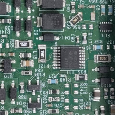
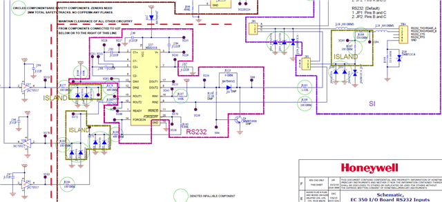
Attached is the Sch for your reference, can you review and help with suggestions to identify this issue. 

 RS232_Circuit.pdf

Regards, S Mathew. 

  • What are the voltages at the RIN pin? Can you show an oscilloscope trace?

    (The /INVALID output shows whether auto-powerdown is active.)

  • Hi Shinu,

    1. Do you have scope shots of the RIN pin and the ROUT pin. Also have they probed the /INVALID pin during there tests as that will verify that the device is receiving valid data? 

    2. can you share a picture of the top of one of the suspect device so I can see the date code and the formatting on the IC markings? 

    Please let me know so I can dig into this issue a bit deeper for you!

    Best,

    Parker Dodson

  • Hi Parker,

    Please find below details shared by customer.

    1. Scope shots of the RIN pin and the ROUT pin. Also probe the /INVALID pin during tests, as that will verify that the device is receiving valid data?  During communication, Rin pin receives command from another device and we could see the same command is coming out of ROUT pin and received at Controller pin. And Controller responds to the received command and it is going till DIN of our Driver but not coming out of DOUT.                                                                                                       
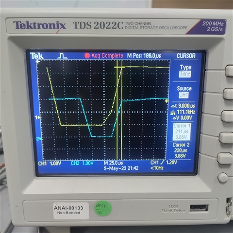
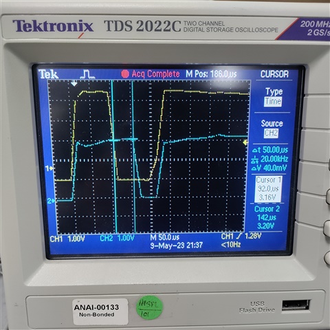
1. Falltime-RIN-INVALID                                     2. Risetime-RIN-INVALID
    1. Can you share a picture of the top of one of the suspect device, our team can verify the date code and the formatting on the IC markings?   Attached Image

    Please find below pin voltages measured. One point customer mentioned is that this issue is observed while communicating with host board (EVC) and this board is having MAX3318. The device is working with USB to RS232 converter. Find below pin voltage difference during operation. 

    CL5G

    MAX3221

    Before Communication

    EVC - MAX3318 During Communication

    USB-RS232 Convertor Cable

    1

    EN

    Low

    Low

    Low

    2

    C1+

    High

    High

    Toggling +6V to 3.5V

    3

    V+

    High

    High

    +6V

    4

    C1-

    Low

    Low

    Toggling +3.5V to GND

    5

    C2+

    Low

    Low

    Toggling +6V to GND

    6

    C2-

    Low

    Low

    Toggling -6V to GND

    7

    V-

    Low

    Low

    -6V

    8

    R_IN

    Low

    -0.6V - Command(Toggle)

    -5.6V

    9

    R_OUT

    High

    High - Command(Toggle)

    +4V

    10

    INVALID

    Low

    w.r.t R_IN

    High

    11

    T_IN

    Low

    High - Response(Toggle)

    Low

    12

    FORCEON

    Low

    Low

    Low

    13

    T_OUT

    Low

    +0.6V

    +6V

    14

    GND

    Low

    Low

    Low

    15

    VCC

    High

    High

    High

    16

    FORCEOFF

    High

    High

    High

    Regards, S Mathew. 

  • The oscilloscope traces show that the minimum RIN voltage is only about −0.7 V. This is invalid and triggers the auto shutdown.

    The voltage of −0.7 V implies that there is a silicon diode between ground and the RIN signal. Typically, this happens when there is a unidirectional TVS diode on the line, but in the schematic, the TVS diode D42 looks correct (it's bidirectional, ±12 V).

    Is there a diode somewhere else? I'd guess such a wrong diode is on the EVC.

    If you cannot change the host board to output correct RS-232 voltages, then you have to disable the auto-shutdown mode.

  • Hi Shinu,

    Okay - so Clemens is correct - it seems that the voltage level is not going low enough and not exiting auto-shutdown mode - most likely this is caused by a diode that isn't seen on the schematic - or there could have been a wrong diode installed. 

    Best,

    Parker Dodson

  • Hi Parker, Clemens,

    Thanks for the comments.

    Please find below schematic of EVM interface. The Diodes are verified on EVC side, they are placed properly.

    Please check if you find any observations from the RS232 Circuit on EVC side.

    Regards, S Mathew. 

  • D30/D31/D34/D35 are wrong; for RS-232, they would have to be bidirectional TVS diodes. (They are also wrong for RS-485, but only for unusual bus voltages.)

    With these diodes, the EC board does not generate valid RS-232 voltages, i.e., it violates the RS-232 standard. Remove them. (This does not even reduce protection; the nearby SMBJ12CA diodes can do their job.)

  • Hi Clemens,

    Customer removed these diodes, still not working.

    They mentioned that,  this EVC board is in filed since 8 years and interfaced to different Modems over RS232 interface with same hardware configuration. We don’t suspect anything wrong with the Diodes in design.

    Regards, S Mathew. 

  • Hi Shinu,

    The issue is that there is a signal that seems to be clamped to -0.7V and there are single ended diodes in the design (which for RS-232 you can only use bi-directional - same goes for RS-485 in most cases) and the RIN pin really doesn't have components that should show that type of clamping when damaged. So I am skeptical on the RS-232 section working as this design breaks one of the main requirements for RS-232 - they may have been using RS-485 in systems where ground shifting is minimal as you probably wouldn't see this problem then - but RS-232 devices at minimum are outputting +/-5V - which excludes any single ended diode from consideration 

    So here are the next steps.

    1. I don't think its the IC - They need to isolate the suspect IC and run it by just passing signals to it from a signal generator - if they are not seeing issues (i.e. the negative voltage being clamped low)  then its 100% a design problem on the board - which is probably the diodes as their use is pretty explicitly banned by the minimal set of requirements of RS-232. 

    2. They need to put a fresh device on the board with no single ended diodes attached and see if there is issue - as it sounds like they ran the same IC - so to eliminate other potential causes of failure use a fresh device and see what the system performs as. Is the signal still being clamped to -0.7V or is the problem something else is popping up - if I get an answer that just says "it doesn't work" I am not going to be able to do much with that - I need to know if the failure signature has changed - because there could be different issues or it could just be the system design. 

    3. If the part, when removed and tested by itself, shows the same signature and a fresh device on the board with the single ended diodes removed it needs to go in for an FA because it could be damaged -but I really don't think that's the case. The system design didn't consider the minimal requirements for RS-232 so I think its unlikely that this is a direct IC issue.

    Best,

    Parker Dodson

  • Hi Parker,

    Thanks for the feedbak.

    Can any series resistor on both Tx & Rx sides limits the current and create this issue?

    Thanks. 

  • Hi Shinu,

    Yes in theory series resistors can be too large compared to RS-232 load and cause issues.

    The reason I don't think that is the issue in this design is two fold:

    1. On the RX path the resistance is 200 ohms - if the DOUT path connecting to the RIN on this device without any additional series resistors you should be seeing worst case drop of ~6% of initial signal (assuming RIN load is worst case impedance - 3k) - the -0.7V signal seems to low in this case.

    2. If DOUT connecting to this device have a similar series output of 1.21k + a 200 ohm  ohm you'd have worst case a little over 33% attenuation - which still doesn't match up with what is being seen - as I doubt the cabling is is adding a lot of series resistance and the current on the line is pretty low.

    3. Unless you are running this device near its minimum temperatures you probably are going to be much closer to 5k Ohms instead of 3k ohms for loading

    4. The biggest issue with this theory  however is that the attenuation should be equivalent if the both sides of the bus have similar designs - if not then I need to see the other side of the system - if it is though then you wouldn't be having this asymmetric result as the logic 0 and logic 1 values should be same magnitude but opposite polarity. 

    Best,

    Parker Dodson

  • Thanks Parker,

    I got it, will check on mentioned point.

    Thanks.