A related question is a question created from another question. When the related question is created, it will be automatically linked to the original question.
If you have a related question, please click the "Ask a related question" button in the top right corner. The newly created question will be automatically linked to this question.
SN75176AD communication issue (micro controller and PC)
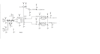
As far as I can see, the wiring of the optocouplers is incorrect and inverts the signals; the LEDs should be driven from the cathode. A digital isolator like the ISO6731 would be cheaper than three optocouplers and would have avoided this problem.
What is the issue that you are seeing - do you have a scope shot to show the problematic behavior? I agree with Clemens - the optocouplers are inverting and a digital isolator may prove to be a better fit in the control facing side of the device.
I also do have a few other questions:
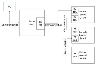
1. How long is the bus?
2. How many RS-485 transceivers are on the bus?
3. Are there terminations elsewhere in the system ?
4. What is the network topology?
Please if you could clarify the above 4 points it will aid in my analysis.
1. You have shown two boxes labelled "RS-485" on the motor board and the barcode board. Are those two transceivers, or two connectors going to the same transceiver?
2. Please specify exactly how the RS-485 lines are terminated.
3. What exactly do you mean with "All board are same time working"? Does this include the RS-485 communication?
4. What exactly do you mean with "command are missing"? Are all or only some commands missing?
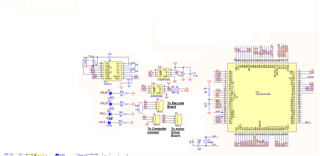
please suggest attached RS485 communication it is OK? (already provided design).
All PCB transmit and receive boud rate is same 38400
point:- You have shown two boxes labelled "RS-485" on the motor board and the barcode board. Are those two transceivers, or two connectors going to the same transceiver?
Ans:- 1 IC use for transmit and received for all board (use this ic transmit and received SN75176AD).
Point:- What exactly do you mean with "All board are same time working"? Does this include the RS-485 communication?
Ans: Main board all board send command same time, in micro-controller program selected motor working as per selected time.
Point:- What exactly do you mean with "command are missing"? Are all or only some commands missing?
Ans :- same command are missing.
but our previous design we have use separate IC for transmit and received and communication is working fine.(attached design)
A scope trace as Clemens also requested of the /RS485_TX_EN, UART_TX, bus A/B signals would be helpful.
That being said - I suspect the issue could possibly due to the enable control of the system as the old system has 1 device for RX in always listening mode - this could be the culprit of the issue. A scope shot of the Enable signal and the A/B signals would be helpful - please if possible on the same scope screen would be great to help identify if there could be an issue with timing.
As per your suggestion we have check command on oscilloscope,
we have send one packed (with 49 command) but received only 37 command.
it is command missing at micro-controller side or RS485?. we can't check full data at oscilloscope (because lot of data at a time send).
Also we check received command at data logger software also command are missing (sending 49 command and received only 37 command).
as per my knowledge is micro-controller send data to RS485 to other micro-controller but data is missing ( reset timer issue) that why instrument are not working.
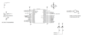
Also we send single command CP2102 module to main board micro-controller also same time data missing. it is timing issue? or reset issue microntroller?
Which commands are missing? The first ones, the last ones, or some random ones in the middle?
If you are not able to reliably send data between the microcontroller and the CP2102, then this has nothing to do with the RS-485 bus. Your suspicion that some microcontroller does not handle the timing correctly might be correct.
So I think there are two issues that could be happening.
1. It is a firmware/timing problem at the controller/MCU level - this means its not the RS-485 bus; since random commands drop it could be how the processing of the bits at the controller level is functioning that is causing the issue.
2. The received voltage is very attenuated and there is some noise present on the bus causing "random" missed bits. I understand you can't capture the entire command sequence on a scope - but if you could even capture 1 or 2 commands on differential receiver (A,B pins) it would help to see what voltage levels are being seen at the receiver - if they are well beyond there thresholds then it is most likely the first issue. Please let me know if you can provide just a small sample of the receiving voltage and that would be very helpful.


 and suggest correct solution.

 .
.
 old communication