This thread has been locked.

If you have a related question, please click the "Ask a related question" button in the top right corner. The newly created question will be automatically linked to this question.

DP83869HM: Not able to access the DP83869 PHY

Part Number: DP83869HM
Other Parts Discussed in Thread: TM4C129DNCPDT, DP83869, USB-2-MDIO, MSP-EXP430G2ET

Hi,

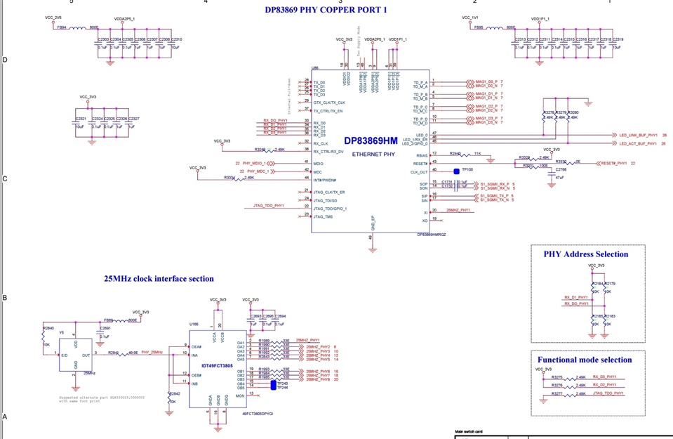
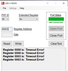
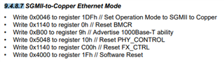
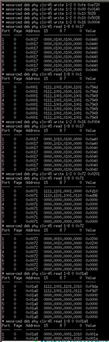
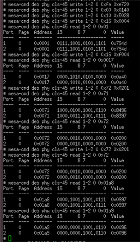
We are using DP83869HM PHY in our board for SGMII to Copper Ethernet Mode. The Strapping configuration has been followed as per the 9.5.1.2 Strap for DP83869HM Functional Mode Selection table in datasheet. The clock and Voltage levels also going proper to the PHY(CLOCK_OUT=25MHz), But still we are not able to detect link. We tried to access the PHY registers using the TM4C129DNCPDT controller but the PHY is not responding i.e., FFFF we are recieving as response. Please help us to access the PHY.

  • Hi Abishake,

    Let's try to debug your register access first since that will provide us with more information to figure out why link is not working. The fact that the registers are reading FFFF could be caused by (1) the PHY not being powered up correctly or (2) accessing the incorrect PHY address. I have a few things for you to try:

    • Make sure you are reading the correct PHY address
    • Probe voltage at RBIAS after power up
    • Go through the attached schematic checklist to make sure your schematic is OK

    3324.DP83869_Schematic_Design_Review_Checklist.xlsx

    Best regards,

    Melissa

  • Hi Melissa,

    We have checked all the voltages input to the DP83869. All are within the range.

    Even the power sequencing also we have done similar to the below image.

    2.5v & 1.1v are immediately powering ON. 3.3V (t2 time) we are able to generate in 20msec.

    The clock input is also 25Mhz. 

    We have probed the clock output also, we are able to get 25Mhz at clock output pin properly.

    The voltage at RBIAS is 0V.

  • Hi Abishake,

    RBIAS should not be 0V at power up, could you use a multimeter to probe the resistor value? It should be within +-1%. 

    Best regards,

    Melissa

  • Hi MElissa,

    We have the checked the resistance value of RBIAS 

    We have fabricated totally 10 sections in our unit. In all places we are able to get the impedance value between 10.91Kohm to 11.07Kohm. We have checked all the values in 6 1/2 DMM.

    Also the voltage at RBIAS is 1V (wrongly mentioned earlier as 0 V)

    please help us to read the registers of DP83869 PHY.

    Regards,

    Abishake

  • Hi Abishake,

    Could you probe the MDIO/MDC signals? If you are able to confirm that you are a valid signal, then it is possible that (1) you are accessing the incorrect PHY address or (2) You are accessing the MDIO/MDC lines incorrectly with the TM4C129DNCPDT, in which case you may have to reach out to the Arm-based microcontrollers team.

    Best regards,

    Melissa

  • Hi Melissa,

    We want to add DP83869HM driver to our application to access the PHY.  In our application code we have Inter PHY driver file(which we are attaching here). So we need to create similar files for our PHY module. 

    Can you help us to create drivers for the DP83869 PHY?

    Regards,

    Abishake

    /*
     Copyright (c) 2004-2022 Microsemi Corporation "Microsemi".
    
     Permission is hereby granted, free of charge, to any person obtaining a copy
     of this software and associated documentation files (the "Software"), to deal
     in the Software without restriction, including without limitation the rights
     to use, copy, modify, merge, publish, distribute, sublicense, and/or sell
     copies of the Software, and to permit persons to whom the Software is
     furnished to do so, subject to the following conditions:
    
     The above copyright notice and this permission notice shall be included in all
     copies or substantial portions of the Software.
    
     THE SOFTWARE IS PROVIDED "AS IS", WITHOUT WARRANTY OF ANY KIND, EXPRESS OR
     IMPLIED, INCLUDING BUT NOT LIMITED TO THE WARRANTIES OF MERCHANTABILITY,
     FITNESS FOR A PARTICULAR PURPOSE AND NONINFRINGEMENT. IN NO EVENT SHALL THE
     AUTHORS OR COPYRIGHT HOLDERS BE LIABLE FOR ANY CLAIM, DAMAGES OR OTHER
     LIABILITY, WHETHER IN AN ACTION OF CONTRACT, TORT OR OTHERWISE, ARISING FROM,
     OUT OF OR IN CONNECTION WITH THE SOFTWARE OR THE USE OR OTHER DEALINGS IN THE
     SOFTWARE.
    */
    
    #include <unistd.h>
    #include <stdint.h>
    #include <stdlib.h>
    #include <stdbool.h>
    
    #include <microchip/ethernet/phy/api.h>
    #include <mepa_driver.h>
    #include <mepa_ts_driver.h>
    
    #include "os.h"
    #include "gpy211.h"
    #include "gpy211_common.h"
    #include "registers/phy/std.h"
    #include "registers/phy/phy.h"
    #include "registers/phy/pmapmd.h"
    #include "registers/phy/pcs.h"
    #include "registers/phy/aneg.h"
    #include "registers/phy/vspec2.h"
    
    #define T_D(format, ...) MEPA_trace(MEPA_TRACE_GRP_GEN, MEPA_TRACE_LVL_DEBUG, __FUNCTION__, __LINE__, format, ##__VA_ARGS__);
    #define T_I(format, ...) MEPA_trace(MEPA_TRACE_GRP_GEN, MEPA_TRACE_LVL_INFO, __FUNCTION__, __LINE__, format, ##__VA_ARGS__);
    #define T_W(format, ...) MEPA_trace(MEPA_TRACE_GRP_GEN, MEPA_TRACE_LVL_WARNING, __FUNCTION__, __LINE__, format, ##__VA_ARGS__);
    #define T_E(format, ...) MEPA_trace(MEPA_TRACE_GRP_GEN, MEPA_TRACE_LVL_ERROR, __FUNCTION__, __LINE__, format, ##__VA_ARGS__);
    
    
    #define TRUE 1
    #define FALSE 0
    
    #define INTL_PHY_CHIPID 0x67c9dc00
    
    typedef struct Intl_Port {
        mepa_device_t *dev;
    } Intl_Port_t;
    
    typedef struct {
        struct gpy211_device initconf;
        struct Intl_Port port_param;
    } INTL_priv_data_t;
    
    #define GPY211_DEVICE(dev) (&(((INTL_priv_data_t *)dev->data)->initconf))
    #define INTL_PORT(dev) (&(((INTL_priv_data_t *)dev->data)->port_param))
    #define PRIV_DATA(dev) ((INTL_priv_data_t *)dev->data)
    
    static int (mdiobus_read)(void *mdiobus_data, uint16_t addr, uint32_t regnum)
    {
        mepa_device_t *dev = ((Intl_Port_t *)mdiobus_data)->dev;
        uint16_t value;
        bool mmd_access = false;
        uint8_t devtype, regaddr;
    
        if (regnum | MII_ADDR_C45) {
            mmd_access = true;
            devtype = regnum >> 16 & 0x1f;
            regaddr = regnum & 0xffff;
        }
    
        if (mmd_access) {
            if (dev->callout->mmd_read(dev->callout_ctx, devtype, regaddr, &value) == MEPA_RC_OK) {
                return value;
            }
        } else {
            if (dev->callout->miim_read(dev->callout_ctx, regnum, &value) == MEPA_RC_OK) {
                return value;
            }
        }
    
        return -1;
    }
    
    static int (mdiobus_write)(void *mdiobus_data, uint16_t addr, uint32_t regnum, uint16_t val)
    {
        mepa_device_t *dev = ((Intl_Port_t *)mdiobus_data)->dev;
        bool mmd_access = false;
        uint8_t devtype, regaddr;
    
        if (regnum | MII_ADDR_C45) {
            mmd_access = true;
            devtype = regnum >> 16 & 0x1f;
            regaddr = regnum & 0xffff;
        }
    
        if (mmd_access) {
            if (dev->callout->mmd_write(dev->callout_ctx, devtype, regaddr, val) == MEPA_RC_OK) {
                return 0;
            }
        } else {
            if (dev->callout->miim_write(dev->callout_ctx, regnum, val) == MEPA_RC_OK) {
                return 0;
            }
        }
    
        return -1;
    }
    
    static bool intl_mode_is_usxgmii(mepa_device_t *dev)
    {
        uint16_t reg_val = 0;
    
        dev->callout->mmd_write(dev->callout_ctx, 0x1e, 0x0006, 0x8800);
        dev->callout->mmd_write(dev->callout_ctx, 0x1e, 0x0007, 0x00d2);
        dev->callout->mmd_read(dev->callout_ctx, 0x1e, 0x0005, &reg_val);
    
        return reg_val == 2 ? true : false;
    }
    
    static mesa_rc intl_if_get(mepa_device_t *dev, mesa_port_speed_t speed,
                               mesa_port_interface_t *mac_if)
    {
        if (intl_mode_is_usxgmii(dev)) {
            *mac_if = MESA_PORT_INTERFACE_QXGMII;
        } else {
            *mac_if = MESA_PORT_INTERFACE_SGMII_2G5;
        }
    
        return MEPA_RC_OK;
    }
    
    static mesa_rc intl_phy_sgmii_conf(mepa_device_t *dev, mepa_status_t *status)
    {
        int rc;
        struct gpy211_device *phy = GPY211_DEVICE(dev);
        struct gpy211_sgmii sgmii;
    
        sgmii.linkcfg_dir = SGMII_LINKCFG_TPI;
        sgmii.aneg_mode = SGMII_ANEG_1000BX;
        sgmii.link.autoneg = 0;
        switch (status->speed) {
        case (MESA_SPEED_2500M):
            sgmii.link.speed = 2500;
            break;
        case (MESA_SPEED_1G):
            sgmii.link.speed = 1000;
            break;
        case (MESA_SPEED_100M):
            sgmii.link.speed = 100;
            break;
        case (MESA_SPEED_10M):
            sgmii.link.speed = 10;
            break;
        default:
            return MESA_RC_ERROR;
        }
    
        rc = gpy2xx_sgmii_config_aneg(phy, &sgmii);
    
        return rc < 0 ? MESA_RC_ERROR : MESA_RC_OK;
    }
    
    static mesa_rc intl_poll(mepa_device_t *dev, mepa_status_t *status)
    {
        struct gpy211_device *intel_status = GPY211_DEVICE(dev);
        bool link_change = false;
    
        if (gpy2xx_update_link(intel_status) < 0) {
            return MESA_RC_ERROR;
        }
        if (gpy2xx_read_status(intel_status) < 0) {
            return MESA_RC_ERROR;
        }
        if (status->link != intel_status->link.link) {
            link_change = true;
        }
        status->link = intel_status->link.link;
        if (status->link) {
            switch (intel_status->link.speed) {
            case (SPEED_1000):
                status->speed = MESA_SPEED_1G;
                break;
            case (SPEED_100):
                status->speed = MESA_SPEED_100M;
                break;
            case (SPEED_10):
                status->speed = MESA_SPEED_10M;
                break;
            case (SPEED_2500):
                status->speed = MESA_SPEED_2500M;
                break;
            default:
                T_E("not expected speed");
                break;
            }
        }
        status->fdx = intel_status->link.duplex;
        status->aneg.obey_pause = intel_status->link.pause;
        status->aneg.generate_pause = intel_status->link.pause;
        status->copper = TRUE;
        status->fiber = FALSE;
        T_D("intl_phy_status_get: link %d, speed %d  duplex %d\n", intel_status->link.link, intel_status->link.speed, intel_status->link.duplex);
    
        if (link_change && status->link) {
            T_D("link change");
            return(intl_phy_sgmii_conf(dev, status));
        }
    
        return MEPA_RC_OK;
    }
    
    static mepa_device_t *intl_probe(mepa_driver_t *drv,
                                     const mepa_callout_t    MEPA_SHARED_PTR *callout,
                                     struct mepa_callout_ctx MEPA_SHARED_PTR *callout_ctx,
                                     struct mepa_board_conf              *board_conf)
    {
        mepa_device_t *dev;
        INTL_priv_data_t *priv;
    
        dev = mepa_create_int(drv, callout, callout_ctx, board_conf, sizeof(INTL_priv_data_t));
        if (!dev) {
            return 0;
        }
    
        priv = dev->data;
        struct gpy211_device *initconf = &(priv->initconf);
    
        priv->port_param.dev = dev;
        priv->initconf.mdiobus_read = mdiobus_read;
        priv->initconf.mdiobus_write = mdiobus_write;
        priv->initconf.mdiobus_data = (void *)&priv->port_param;
        priv->initconf.lock = NULL;
    
        T_D("intl_probe, enter\n");
        if (gpy2xx_init(initconf) < 0) {
            T_E("intl phy init error\n");
        }
    
        return dev;
    }
    
    static mesa_rc intl_delete(mepa_device_t *dev)
    {
        return mepa_delete_int(dev);
    }
    
    static mesa_rc intl_reset(mepa_device_t *dev,
                              const mepa_reset_param_t *rst_conf)
    {
        return MEPA_RC_OK;
    }
    
    static mesa_rc intl_conf_set(mepa_device_t *dev,
                                 const mepa_conf_t *config)
    {
        int rc;
        struct gpy211_device *phy = GPY211_DEVICE(dev);
    
        if (!config->admin.enable) {
            // Force link down by removing all capablities
            phy->link.autoneg = 1;
            phy->link.advertising = 0;
            rc = gpy2xx_config_aneg(phy);
            return rc ? MEPA_RC_ERROR : MEPA_RC_OK;
        }
    
        phy->link.advertising = 0;
        if (config->aneg.speed_10m_hdx) {
            phy->link.advertising |= GPY2XX_ADVERTISED_10baseT_Half;
        }
        if (config->aneg.speed_10m_fdx) {
            phy->link.advertising |= (uint64_t)GPY2XX_ADVERTISED_10baseT_Full;
        }
        if (config->aneg.speed_100m_hdx) {
            phy->link.advertising |= GPY2XX_ADVERTISED_100baseT_Half;
        }
        if (config->aneg.speed_100m_fdx) {
            phy->link.advertising |= GPY2XX_ADVERTISED_100baseT_Full;
        }
        if (config->flow_control) {
            phy->link.advertising |=  GPY2XX_ADVERTISED_Pause;
            phy->link.advertising |=  GPY2XX_ADVERTISED_Asym_Pause;
        }
        if (config->aneg.speed_1g_hdx) {
            phy->link.advertising |= GPY2XX_ADVERTISED_1000baseT_Half;
        }
        if (config->aneg.speed_1g_fdx) {
            phy->link.advertising |= (uint64_t)GPY2XX_ADVERTISED_1000baseT_Full;
        }
        if (config->aneg.speed_2g5_fdx) {
            phy->link.advertising |= GPY2XX_ADVERTISED_2500baseT_Full;
            phy->link.advertising |= 1 << 15;
        }
    
        switch (config->speed) {
        case MESA_SPEED_10M:
            phy->link.speed = SPEED_10;
            break;
        case MESA_SPEED_100M:
            phy->link.speed = SPEED_100;
            break;
        case MESA_SPEED_1G:
            phy->link.speed = SPEED_1000;
            break;
        case MESA_SPEED_2500M:
            phy->link.speed = SPEED_2500;
            break;
        case MESA_SPEED_AUTO:
            /* in auto mode, link.speed is the resolved speed */
            break;
        case MESA_SPEED_UNDEFINED:
        default:
            T_E("Illegal speed");
            return MESA_RC_ERROR;
        }
    
        if (config->fdx) {
            phy->link.duplex = DUPLEX_FULL;
        } else {
            phy->link.duplex = DUPLEX_HALF;
        }
    
        if (config->speed == MESA_SPEED_AUTO) {
            phy->link.autoneg = 1;
        } else {
            phy->link.autoneg = 0;
        }
    
        rc = gpy2xx_config_aneg(phy);
    
        return rc ? MEPA_RC_ERROR : MEPA_RC_OK;
    }
    
    static mesa_rc intl_status_1g_get(mepa_device_t    *dev,
                                      mesa_phy_status_1g_t *status)
    {
        return MEPA_RC_OK;
    }
    
    static mepa_rc intl_info_get(mepa_device_t *dev, mepa_phy_info_t *const phy_info)
    {
        phy_info->cap = 0;
        phy_info->part_number = dev->drv->id;
        phy_info->revision = dev->drv->id & 0xF;
        phy_info->cap |= MEPA_CAP_SPEED_MASK_2G5;
        return MEPA_RC_OK;
    }
    
    static mepa_rc intl_miim_read(mepa_device_t *dev, uint32_t address, uint16_t *const value)
    {
        return dev->callout->miim_read(dev->callout_ctx, address, value);
    }
    
    static mepa_rc intl_miim_write(mepa_device_t *dev, uint32_t address, uint16_t value)
    {
        return dev->callout->miim_write(dev->callout_ctx, address, value);
    }
    
    static mepa_rc intl_mmd_read(mepa_device_t *dev, uint32_t address, uint16_t *const value)
    {
        uint16_t page_mmd = (address >> 16) & 0xffff;
        uint16_t addr = address & 0xffff;
    
        return dev->callout->mmd_read(dev->callout_ctx, page_mmd, addr, value);
    }
    
    static mepa_rc intl_mmd_write(mepa_device_t *dev, uint32_t address, uint16_t value)
    {
        uint16_t page_mmd = (address >> 16) & 0xffff;
        uint16_t addr = address & 0xffff;
    
        return dev->callout->mmd_write(dev->callout_ctx, page_mmd, addr, value);
    }
    
    static mepa_rc intl_event_enable_set(mepa_device_t *dev, mepa_event_t event,
                                         mesa_bool_t enable)
    {
        uint16_t mask = 0;
    
        if (event == MESA_PHY_LINK_FFAIL_EV) {
            mask |= 1; // Link down IRQ
        }
        return dev->callout->mmd_write(dev->callout_ctx, 0, 25, mask);
    }
    
    static mepa_rc intl_event_poll(mepa_device_t *dev, mepa_event_t *status)
    {
        uint16_t value;
    
        dev->callout->mmd_read(dev->callout_ctx, 0, 26, &value);
        *status = (value & 0x1) ? MESA_PHY_LINK_FFAIL_EV : 0;
        return MEPA_RC_OK;
    }
    
    static mesa_rc intl_if_set(mepa_device_t *dev,
                               mesa_port_interface_t mac_if)
    {
        mesa_port_interface_t int_if;
    
        intl_if_get(dev, 1, &int_if);
    
        if (mac_if == MESA_PORT_INTERFACE_SGMII) {
            mac_if = MESA_PORT_INTERFACE_SGMII_2G5;
        }
        if (mac_if != int_if) {
            T_E("Configured phy interface mode (%d) does not match phy pin strapping (%d)", mac_if, int_if);
            return MEPA_RC_ERROR;
        }
    
        return MEPA_RC_OK;
    }


    mepa_drivers_t mepa_intel_driver_init()
    {
    #define NR_INTL_PHY 1
        mepa_drivers_t res;
        static mepa_driver_t intl_drivers[NR_INTL_PHY] = {};
    
        intl_drivers[0].id = INTL_PHY_CHIPID;
        intl_drivers[0].mask = 0xffff0000;
        intl_drivers[0].mepa_driver_delete = intl_delete;
        intl_drivers[0].mepa_driver_reset = intl_reset;
        intl_drivers[0].mepa_driver_poll = intl_poll;
        intl_drivers[0].mepa_driver_conf_set = intl_conf_set;
        intl_drivers[0].mepa_driver_if_get = intl_if_get;
        intl_drivers[0].mepa_driver_power_set = NULL;
        intl_drivers[0].mepa_driver_cable_diag_start = NULL;
        intl_drivers[0].mepa_driver_cable_diag_get = NULL;
        intl_drivers[0].mepa_driver_media_set = NULL;
        intl_drivers[0].mepa_driver_probe = intl_probe;
        intl_drivers[0].mepa_driver_aneg_status_get = intl_status_1g_get;
        intl_drivers[0].mepa_driver_phy_info_get = intl_info_get,
        intl_drivers[0].mepa_driver_clause22_read = intl_miim_read,
        intl_drivers[0].mepa_driver_clause22_write = intl_miim_write,
        intl_drivers[0].mepa_driver_clause45_read  = intl_mmd_read,
        intl_drivers[0].mepa_driver_clause45_write = intl_mmd_write,
        intl_drivers[0].mepa_driver_event_enable_set = intl_event_enable_set,
        intl_drivers[0].mepa_driver_event_poll = intl_event_poll,
        intl_drivers[0].mepa_driver_if_set = intl_if_set,
    
        res.phy_drv = intl_drivers;
        res.count = NR_INTL_PHY;
    
        return res;
    #undef NR_INTL_PHY
    }
    
    phy_driver.h

  • Hi Abishake,

    Were you able to probe the MDC/MDIO signals to confirm you are seeing a valid signal?

    Unfortunately the only driver we have for the DP83869 is the linux driver, which can be found here: ETHERNET-SW Driver or library | TI.com. For Intel driver support, please reach out to the Intel team. 

    Best regards,

    Melissa

  • Hi Melissa,

    Sorry for late reply. We have connected the MSP-EXP430G2ET launchpad's pi.4 and p1.5 pins to mdc and mdio of DP83869 phy to access the registers directly. We have followed the steps in the USB-2-MDIO Software Tool document. As per the document we have configured the flasher and GUI steps we have implemented. The green and red led are glowing without blinking. In the GUI if I try to read PHY ID its showing NOT available and if  any register data i try to access it is showing  error device not connected is comming. We used scope to trace the clk/data from the msp430 board, but no responce. Can you help us to read the DP83869HM PHY's register using the MSP430 launchpad?

     USB-2-MDIO Software Tool document:  www.ti.com/.../snlu197.pdf

  • Hi Abishake,

    Is the board communicating with the GUI?  I checked the USB-2-MDIO user's guide and see that for G2 launchpads you do need to check and probably rotate the UART pins.  

    Please review that and let me know that it looks configured correctly.  

    Thanks,

    Melissa

  • Hi Melissa,

    Thanks for your response. The board is communicating  to the GUI. We  have rotated the UART pins, but now we are recieving Timeout error while trying to read the register. Please see the attached screenshot.

    We are probing the MDC/MDIO pins while reading, but we are not able to get any waveform on dso. while reading the green and red led's on msp430 board will blink. Is source code available anyware for msp430 board?

  • Hi Abishake,

    I have a few things for you to try:

    What order are you connecting together and powering up the PHY and MSP430 in? Can you try adjusting this?

    - Can you verify connectivity on MDIO and MDC pins between MSP430 and DP83822 using a multimeter continuity tester?

    - Can you connect the MSP430 ground pin to pin 22 or pin 24 of J14 connector and try again?

    - Could you provide a picture of your setup?

    Best regards,

    Melissa

  • Hi Melissa,

    We are able to read/write the PHY from the switch's MDC/MDIO. When a ethernet cable is connected we are able to get link up for the respective port with speed as 1Gfdx. But we are not able to get any packets transmission between the ports. I'll mention some of the register read below. We are using 8 DP83869HM PHY's in our board, each pin strapped for SGMII to COPPER mode.

    0x0:  0x1140
    0x1:  0x796d
    0x4:  0x0de1
    0x5:  0xc5e1
    0x7:  0x2001
    0x8:  0x4df8
    0x9:  0x0300
    0xA:  0x0800
    0xF:  0xf000
    0x10: 0x5048

    Can you tell us what are the registers need to be modified to acheive the data transmission between the ports in SGMII to COPPER mode?

  • Hi Abishake,

    Here are the register writes required for SGMII to Copper mode, in section 9.4.8.7 of the datasheet:

    Best regards,

    Melissa

  • Hi Melissa,

    I have already followed the same steps from the datasheet. But still I am not able to transmit any packets between ports. Is there any way to check weather the PHY and ingress/egress ports are able to communicate ? and PHY is able to communicate with the switch?

  • Hi Abishake,

    What is your full setup, would it be possible to provide a block diagram?

    Could you also provide registers 0x14 and 0x37?

    Is there any way to check weather the PHY and ingress/egress ports are able to communicate ? and PHY is able to communicate with the switch?

    You can check that your MDI communication is working through Reverse Loopback mode. Reverse loopback will take data coming from the cable side and send it back across the cable. You can read more about it in section 9.3.4.1.6 Far-End (Reverse) Loopback of the datasheet. You can enable this mode thru register 16. If this works, the problem likely lies with your MAC. 

    .Best regards,

    Melissa

  • Hi Mallissa,

    Please find the readings of registers below:

    Register 0x14 - 0x29c7

    Register 0x37 - 0x0000

    I have also read about Far-End(Reverse) loopback mode from datasheet. So what value I have set to Register 0x16 to enable Far-End loopback mode in our system. And also do we need to configure or change any other registers settings to verify this. And after configuring how verify the working of this mode?

    And also I have attached our block diagram of board. Please look into it.

    Thank You.

    Regards,

    Abishake

    BLOCK DIAGRAM_SAMPLE CARD-DP83869-TEXAS.pdf

  • Hi Abishake,

    Register 0x37 shows that SGMII auto-negotiation is incomplete, which points this being a MII side issue instead of a MDI side issue. I recommend adjusting the autonegotiation time and restarting SGMII autonegotiation.

    You can try configuring the SGMII autonegotiation time in register 0x31[6:5] and reset SGMII in 0x14[12]

    For reverse loopback, you would have to connect your PHY to a link partner, enable Reverse Loopback in register 0x16[5:2], and then send packets from the link partner to the PHY and confirm that the link partner receives the packets back. See the datasheet register description for more information on the specific bit configuration. 

    Best regards,

    Melissa

  • Hi Melissa,

    I have tried with altering the register 0x31[6:5] and reset SGMII in 0x14[12] in all four combinations, but the register 0x37 register status is not changing(still 0x0000).

    But in the 9.6.1.18 INTERRUPT_STATUS Register (Offset = 13h) register if cable is connected i am receiving 0x1c40, which indicates Auto negotiation is completed. Does this register is indicating SGMII auto negotiation?

    Can you suggest any other methods to get the auto negotiation complete status in 0x37.  

    One more thing, In the reverse loopback I am setting the register 0x16[5:2] in to reverse loopback mode. After that how should I send packets to the PHY.  Should I have to send any random packets from the link partner? Do I have to connect a laptop to the respective port where loopback is setted or do I have to configure another PHY into PRBS packet generation mode and connect cable between this two PHY's? Please explain the full setup for this loopback test.

  • Hi Abishake,

    Would you be able to measure the eye of your SGMII signal?

    To enable reverse loopback mode to test the MDI lines, follow these steps:

    1. Connect your PHY A to another PHY B, enable Reverse Loopback in register 0x16[5:2] on PHY A

    2. Send packets from PHY B to PHY A. You can do this by enabling continuous PRBS packet generation in register 0x16[15:12].

    3. Enable  the PRBS TX checker in bit 0x39[0]. Confirm that the link partner receives packets back without error. You can check the status of your PRBS packets in 0x17, 0x39, and 0x3A. 

    Best regards,

    Melissa

  • Hi Melissa,

    I have followed the steps you suggested. In PHY A i enabled reverse loopback by writing 0X0020 and in PHY B I enabled PRBS packet generation by writing 0xF000. In 0x39 I have written 0x0001. After these modifications I checked 0x17,0x39, and 0x3A registers. In 0x17 register for PHY B value comming as 0x0a40(which is indicating PRBS lock sync and packet generation process). In 0x3A register it is not updating any value(0x0000).  Why does the PRBS tx count not showing in the 0x3A register? I tried to set 0x39(1) bit also.

    Note: After writing 0xf000 to PHY B 0x16 register, Both port's activity LED started glowing continuously.

    If based on above observation the Far-end Loopback is working means, can we proceed with near-end loopback? Please help us to check the data transmission between MAC and the PHY.


    Would you be able to measure the eye of your SGMII signal?

    No. In our lab we are not having setup for measuring the 1G SGMII signals. But the same 1G SGMII signals are connected to direct SFP Ports (Which are running around 4inch traces, which are working fine. 

  • Hi Abishake,

    To enable the counter in register 0x3A, set 0x39[0] to 1. 

    If you want to enable near-end loopback, 

    1. Power and connect the PHY to the MAC.

    2. Enable analog loopback on the PHY (regiser 0x16[5:2])

    3. Transmit test packets from the MAC to the PHY. 

    4. Verify the MAC receives the same test packets.

    To measure your SGMII signal, all you should need is a differential probe (with built in 100 Ohm termination) and a scope. Probing this signal would help us debug your MAC to PHY communication. 

    Do you think you would be able to provide your Ethernet PHY section of your schematic?

    Best regards,

    Melissa

  • Hi Melissa,

    Thanks for your response. I have setted the 0x39(0) bit also. But I am not able to get any counter in 0x3A register. 

  • Hi Melissa,

    I have tried to enable the analog loopback by writing 0x0008 to 0x16 register. After writing this register the link status is become down. In that state I am not able to send Packets from MAC to the PHY. In our switch if link is UP only we can send frames from the switch MAC to the PHY. Shall I follow the MII loopback method to verify the MAC-PHY  communication.

    I have attached the Schematics for your reference. And Still I am not able to get any counter in the 0x3A register even after writing the 0x39(0) bit.DP83869_SCH.pdf

  • Hi Abishake,

    Apologies, I was mistaken as the register description for 0x3A needs to be clarified in the datasheet, it does not count incoming packets from the MDI interface. Let me check with our internal team if any such registers exist. I will get back to you by tomorrow.

    Thank you for providing your schematic, I will get back to you by tomorrow about it aswell. Have you checked your board follows the recommendations outlined in this app note, specifically the ones mentioned in the MII section? https://www.ti.com/lit/an/snla387/snla387.pdf 

    Best regards,

    Melissa

  • Hi Melissa,

    I have followed a ti query regarding DP83869 loopback. 

    e2e.ti.com/.../dp83869hm-dp83869-cannot-correctly-recognize-the-setting-mode-and-the-network-port-cannot-communicate

    I have altered the registers as follows,

    00FE E720
    0000 0140
    0010 5008
    0016 0008
    001F 4000

    Read register 0001 for the link-up status.

    I have altered the PHY 1 and PHY 2 with these register values, and while reading 0x01 register I am able to get link up for both the phy's . It may help you to debug the issue.

    Note : No cables is connected to the ports.

  • Hi Abishake,

    Thank you for providing these test results - this should confirm that your MDI side is working OK.

    Your schematic looks OK however I am wondering about your routing for your SGMII port routing. Did you follow these guidelines mentioned in the MII section? https://www.ti.com/lit/an/snla387/snla387.pdf 

    For the MAC side, here is a test procedure for you to try:

    1. Set Digital Loopback (write register 0x0016 to 0x0004)
    2. Wait for link-up
    3. Enable PRBS Transmit and checker towards copper (write register 0x0016 to 0xF004)
    4. Wait for PRBS Lock (Wait till bit[11] of register 0x0017 is set to 1’b1)
    5. Read the packet statistics
      1. Write register 0x0072 to 0x0201 to latch the statistics
      2. Read the below registers
        1. 0x0071  (PRBS Byte Count)
        2. 0x0072 (bit[7:0] is error count)
        3. 0x01a8 (Packet Count)
        4. 0x01a9 (packet Count)

    Best regards,

    Melissa

  • Hi Melissa,

    Thanks for the response. We are following exactly as mentioned in the MII guidelines document. I will check the MAC side loopback as you suggested and I'll get back to you.

  • Hi Melissa,

    I have performed the Digital loopback test by following the steps you suggested and by reffering a ti thread. 

     https://e2e.ti.com/support/interface-group/interface/f/interface-forum/1102478/dp83869hm-setting-up-digital-loopback-confirming-results/4111747#4111747

    Steps followed:

    1. Set Digital Loopback (write register 00FE to E720, Register 0000 to 0140, register 0010 5028, register 0x0016 to 0x0004)
    2. Wait for link-up
    3. Enable PRBS Transmit and checker towards copper (write register 0x0016 to 0xF004)
    4. Wait for PRBS Lock (Wait till bit[11] of register 0x0017 is set to 1’b1)
    5. Read the packet statistics
        a. Write register 0x0072 to 0x0201 to latch the statistics
        b. Read the below registers
            i. 0x0071 (PRBS Byte Count)
            ii. 0x0072 (bit[7:0] is error count)
            iii. 0x01a8 (Packet Count)
            iv. 0x01a9 (packet Count)

    Results:

    After writing the registers 0xFE(0xe720), 0x00(0x0140),0x10(0x5028) and 0x16(0x0004) the link-up is comming for the respective PHY's(1 and 2) by reading the 0x1 register. Then I modified the 0x16 register as 0xf004 and checked the 0x17 for PRBS lock. 11th bit is 1.

    After these steps written 0x72 register with 0x201, and read the registers 0x72,0x71,0x01a8 and 0x01a9. In which 0x72(7:0) is always 00 only. other register statuses is getting updated. Please see the screenshot attached above.

    Does this test proves the communication between MAC and PHY is working?

    What other test can we try to get the data properly transfer between MAC to PHY?

  • Hi Abishake,

    This test is used to test the MAC and PHY connection. It is odd that your SGMII link is down while this test passes and you are able to communicate with SFP modules. Is register 0x37 still 0x0? Have you tried reading it multiple times?

    Could you try the same exact test as before but in Analog loopback instead of digital loopback mode?

    Are you trying different cables?

    But we are not able to get any packets transmission between the ports.

    What were the setups you did to try to transmit packets between the ports? How was the PHY configured and how was the VSC7464-02 configured?

    Best regards,

    Melissa

  • Hi Melissa,

    Sorry for the misunderstanding. In our board we have 8 DP83869HM PHY's. I have written registers for PHY 1 and 2 only in previous reply. If you see the register read for 0x1 port 1 and 2 will be showing link up. I am attaching screenshot for register read/write for two phy's below.

    What were the setups you did to try to transmit packets between the ports? How was the PHY configured and how was the VSC7464-02 configured?

    I tried to send frames from the switch(MAC -> PHY) to the respective loopback ports. Only the Tx count is increasing and Rx is 0 only.

    The DP83869 PHY's are pin strapped to operate in SGMII to copper mode. Even in register read also we are able to confirm the PIN strapping(register 0x6E -> 0x0c00).

    The VSC7464 is programmed with mesa application in that I have created a driver for DP83869 to work with that PHY. After adding the driver only we are able to read and write the PHY registers. The switch has 8 Electrical ports, 4 1G SFP ports and 4 10G SFP+ ports. In these 1G SFP and 10G SFP+ are directly connected with the switch and we are able to see packet transfer in these ports. The 8 Electrical ports are connected through the DP83869 PHY's.  If in any electrical port cable is connected, the Link and Activity LED's are working properly but data transfer is not happening(ping test is failing).

    Please help us to get packet transfer between the ports.

  • HI Abishake,

    Thank you for your detailed reply. I will have to consult my team more on this issue and get back to you tomorrow.

    I have tried with altering the register 0x31[6:5] and reset SGMII in 0x14[12] in all four combinations, but the register 0x37 register status is not changing(still 0x0000).

    In the meantime, I realized the register I provided before 0x14[12] does a soft reset pulse of SGMII, but not a full restart of SGMII autoneg. This is done through 0xc00[9]. Apologies, but could you try this write again through register 0xc00[9]?

    Best regards,

    Melissa

  • Hi Abishake,

    We have seen cases before where the SGMII signal needs to be adjusted in order for communication to work. In order to determine this, we must have a measurement of the signal. Does your lab have a differential probe and scope? We can walk  you through the steps to measure the signal if you do. 

    Do you also happen to have your layout/gerber file?

    Also was there a particular reason you developed your own driver instead of using the linux driver?

    Best regards,

    Melissa

  • Hi Melissa,

    We don't have the scope with capability to measure the SGMII signal. Can you help us go through each loopback test to isolate the issue. Because as we already did far end loopback, in near end loopback we have confirmed digital loopback the prbs lock and packet transfer is happening.

    Can we proceed with PCS ,analog and MII loopback to test the MAC - PHY connectivity. Please provide us the step by step register write for each loopback method and register read to verify weather loopback is working properly or not.

    I am attaching the gerber file with this comment.

    The reason for us to write our own driver is because we are using the switch application(mesa) which will only support its own driver(insted of sample linux driver). The driver which we have created is able read/write the PHY's direct and extended registers. So I think driver may not cause any issue for the data transfer between PHY and Switch. We are comparing the sample linux driver register read/write with our driver.

    Do you think weather the 0x37 register SGMII autonegotiation may affect the data transmission? Is there any delay we should give before writing the reset register after altering the SGMII autonegotiation time(0x31)?


    5047-D-03-GERBER.rar

  • Hi Abishake,

    Would be able to get access to a scope with such capabilities?

    If digital loopback works, PCS and MII loopback should also work. You can try analog loopback using the same steps you used for digital loopback, but enable the PHY in analog loopback instead of digital loopback mode. 

    Thanks for attaching the Gerber file, I will provide feedback on Wednesday. 

    Do you think weather the 0x37 register SGMII autonegotiation may affect the data transmission? Is there any delay we should give before writing the reset register after altering the SGMII autonegotiation time(0x31)?

    Yes, register 0x37 shows that SGMII auto negotiation is not complete and SGMII auto negotiation must be successful for data transmission. Yes, try adding a small delay to see if that works. 

    Best regards,

    Melissa