This thread has been locked.

If you have a related question, please click the "Ask a related question" button in the top right corner. The newly created question will be automatically linked to this question.

TCAN4550EVM: Trouble in establishing communication to TCAN4550EVM with STM32F407VET6

Part Number: TCAN4550EVM
Other Parts Discussed in Thread: MSP430FR6989, TCAN4550

Hello,

I am trying to connect TCAN4550EVM to my STM32F407VET6 board and I'm stuck in the first step. I can't even read the device ID correctly. What I got from address 'h000 & 'h0004 are random values.

I'm able to use USART and COM function and read the device id of a flash memory on my MCU board, so the MCU itself is not broken. 

The compiler I'm using is Keil V5 Lite. The code sample on the website seems to be for other compiler and MCU so I cannot use it directly. I simplified my code to SPI-related and hope someone could check out anything wrong. I have very limited experience in MCU application. Maybe they are simple mistakes.

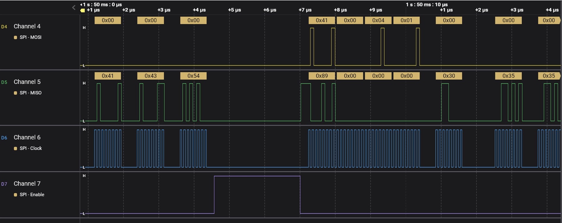
I set the SPI frequency to 10MHz(APB clock is 80Mhz), CPHA=0, CPOL=0. Only 6 wires are connected: VBAT and GND to a 12V power supply, SCLK to PA5, SDI to PA7, SDO to PA6, nCS to PA4.

void SPISendByte(unsigned char tmpData)
{
	while((SPI1->SR&2)==0);		//wait for TXE
	SPI1->DR = tmpData;
}
unsigned char SPIGetByte()
{
	while((SPI1->SR&2)==0);		//wait for TXE
	while(SPI1->SR&(1<<7));		//wait for !BSY
	SPI1->DR = 0;		//send dummy data
	while(!(SPI1->SR&1));		//wait for RXNE
	return SPI1->DR;
}

void TCANReadBytes(unsigned short address, unsigned char *tmpC, unsigned short len1)
{
	GPIOA->BSRRH |= GPIO_Pin_4;		//set to 0, enable
	SPISendByte(0x41);		//read
	SPISendByte(address>>8);		//MSB
	SPISendByte(address&0xFF);		//LSB
	SPISendByte(len1);		//len1*32bit
	while((SPI1->SR&2)==0);		//wait for TXE
	while(SPI1->SR&(1<<7));		//wait for !BSY
	SPI1->DR;		//read the last dummy byte
	for (unsigned short idx1=0; idx1<len1*4; ++idx1)
		tmpC[idx1] = SPIGetByte();
	GPIOA->BSRRL |= GPIO_Pin_4;		//set to 1, disable
}

int main(void)
{
	NVIC_PriorityGroupConfig(NVIC_PriorityGroup_2);
	USART1_Init(115200);

	//SPI settings
	RCC->AHB1ENR |= RCC_AHB1Periph_GPIOA;
	GPIO_InitTypeDef GPIO_InitStructure;

	GPIO_InitStructure.GPIO_Pin   = GPIO_Pin_4;		//nCS
	GPIO_InitStructure.GPIO_Speed = GPIO_Speed_50MHz;
	GPIO_InitStructure.GPIO_Mode  = GPIO_Mode_OUT;
	GPIO_InitStructure.GPIO_OType = GPIO_OType_PP;
	GPIO_InitStructure.GPIO_PuPd  = GPIO_PuPd_UP;
	GPIO_Init(GPIOA, &GPIO_InitStructure);
	
	GPIOA->BSRRL |= GPIO_Pin_4;		//set to 1, disable NCS
	
	GPIO_InitStructure.GPIO_Pin = GPIO_Pin_5 | GPIO_Pin_6 | GPIO_Pin_7;
	GPIO_InitStructure.GPIO_Mode = GPIO_Mode_AF;
	GPIO_InitStructure.GPIO_OType = GPIO_OType_PP;
	GPIO_InitStructure.GPIO_PuPd = GPIO_PuPd_NOPULL;
	GPIO_Init(GPIOA, &GPIO_InitStructure);
	
	GPIO_PinAFConfig(GPIOA, GPIO_PinSource5, GPIO_AF_SPI1);
	GPIO_PinAFConfig(GPIOA, GPIO_PinSource6, GPIO_AF_SPI1);
	GPIO_PinAFConfig(GPIOA, GPIO_PinSource7, GPIO_AF_SPI1);
	
	RCC->APB2ENR |= (1<<12);		//enable SPI1 clock
	SPI1->CR1 |= 0 << 0;		//CPHA = 0
	SPI1->CR1 |= 0 << 1;		//CPOL = 0
	SPI1->CR1 |= 1 << 2;		//master mode
	SPI1->CR1 |= 2 << 3;		//baudrate = fPCLK /8
	SPI1->CR1 |= 0 << 7;		//MSB first
	SPI1->CR1 |= 1 << 9;		//software slave management
	SPI1->CR1 |= 1 << 8;		//software slave internal
	SPI1->CR1 |= 0 << 10;		//RXonly =0, full-duplex
	SPI1->CR1 |= 0 << 11;		//frame format: 8 bit data
	SPI1->CR1 |= 1 << 6;		//enable external
	
	unsigned char tmpC[5];
	tmpC[4] = 10;
	for(int idx1=0;idx1<8;idx1=idx1+4)
	{
		tmpC[0] = 0;
		tmpC[1] = 0;
		tmpC[2] = 0;
		tmpC[3] = 0;
		TCANReadBytes(idx1, tmpC, 1);
		USART1SendChar((char*)tmpC, 5);		//send the response to PC via COM port
	}

	while (1)
	{
	}
}


The responses are
[2023-07-20 10:43:10.502]# RECV HEX>
00 00 00 00 0A C0 7F F2 40 0A
[2023-07-20 10:43:12.824]# RECV HEX>
FF FF EA 00 0A 02 00 00 00 0A
[2023-07-20 10:43:15.247]# RECV HEX>
FF FF 92 00 0A 02 00 00 00 0A
[2023-07-20 10:43:17.708]# RECV HEX>
FF FF F5 40 0A 02 00 00 00 0A
[2023-07-20 10:43:20.001]# RECV HEX>
FF FF 92 00 0A 00 00 00 00 0A
[2023-07-20 10:43:23.255]# RECV HEX>
00 00 00 00 0A 00 00 00 52 0A
[2023-07-20 10:43:25.510]# RECV HEX>
FF FF 89 00 0A 00 01 39 05 0A
[2023-07-20 10:43:27.581]# RECV HEX>
00 00 00 00 0A 00 00 00 00 0A
[2023-07-20 10:43:29.656]# RECV HEX>
00 00 00 00 0A 00 00 00 00 0A
[2023-07-20 10:43:31.665]# RECV HEX>
00 00 00 00 0A 00 00 00 00 0A
[2023-07-20 10:43:33.786]# RECV HEX>
00 00 00 00 0A 00 00 00 00 0A
[2023-07-20 10:43:35.888]# RECV HEX>
00 00 00 00 0A 00 00 00 00 0A
[2023-07-20 10:43:38.188]# RECV HEX>
7F FF FF FF 0A C4 80 00 00 0A
[2023-07-20 10:43:40.176]# RECV HEX>
FF FF 92 00 0A 00 01 39 05 0A

I tried to read the TCAN ID during the start of MCU and tested it with the reset button of MCU board.

  • Hello Reko,

    The TCAN4550 demo code was developed using Code Composer Studio and the MSP430FR6989 MCU.  However, most of the code is ANSI-C and can be ported as-is to any application.  The firmware GPIO pin control and SPI drivers will have to be modified to match the application's MCU, such as the  STM32F407VET6 in your case.

    Do you have the ability to monitor the SPI signals with a scope or logic analyzer?  If so they should match the SPI Read and Write figures in the datasheet that show the byte sequence that needs to be followed.  Note, there are two words of data for a single register read/write transaction and the nCS pin must remain low for the entire 64-bits.  It can't transition high between the 32-bit words which is a common observation when debugging the SPI driver code.

    Note that the datasheet figures show a double register write or read which sets the "LENGTH" byte in the first (header) word that will indicate there will be 2 (data) words to write or read.  For a single register read, you will set the LENGTH byte to 0x01 and then only hold the nCS pin down for a single 32-bit word of data.

    Can you share the scope or logic analyzer plots of all SPI signals, and or the simultaneous MOSI and MISO data for review?  Just seeing the received response doesn't let me know what the actual SPI signals are including the MOSI data that is sent to the TCAN4550.  If the MOSI data is not in the correct format, the TCAN4550 will not return valid data.

    Regards,

    Jonathan

  • Thank you for your advice. The logic analyzer is a very useful tool. I borrowed one from my colleague and found my nCS pin abnormal. I changed nCS to another pin and the basic communication was established.

    But I also found other 2 problems.

    1. After power on for about 5min, TCAN returns all zeros instead of the correct ID. LED of nINT & nWKRQ went off and INH ON. Other functions may also have stopped.

    Besides the SPI wires, I also connected 5V of TCAN to MCU board 5V and VIO to MCU 3.3V. The MCU board can be powered by the 5V pin or the usb cable from PC. A push on the reset button makes it normal, in which nINT & nWKRQ were ON and INH was OFF. I found this issue similar to TCAN4550EVM: Trouble interfacing with MCU - Interface forum - Interface - TI E2E support forums, but I haven't configured TCAN and no CAN cable is connected.

    If TCAN is powered up without MCU connected, LEDs of INH, GPO2, nINT, GPIO1 went ON and nWKRQ OFF 5min after power on. And in this status, the reset button doesn't work. The board must be reset by the power supply.

    Is this behavior normal? I don't find a state changing logic in the manual and none of the function modes fits the LED status above.

    2. Your code sample uses 'WAIT_FOR_IDLE' during reading SPI data. I copied this logic and transformed it to 'while(SPI1->SR&(1<<7));'(I learned it here: controllerstech.com/spi-using-registers-in-stm32/). But the logic analyzer shows that this line pauses the SPI clock for a while.

    As far as I know, MCUs from ST and TI are both based on ARM so they should act in a similar way. So I guess 'WAIT_FOR_IDLE' doesn't equal 'while(SPI1->SR&(1<<7));'. I found '#define WAIT_FOR_IDLE while ((HWREG16(SPI_HW_ADDR + OFS_UCBxSTATW) & UCBUSY))' but I don't find the value of UCBUSY. How do you think I should interpret 'WAIT_FOR_IDLE'? Though I'm not using code composer, I guess you are able to understand both compilers.

  • Hello Reko,

    The answer to your first question is the device is entering Sleep Mode due to the time out of the Sleep Wake Error (SWE) Timer which is one of the device's Failsafe features.  Please refer to the 8.4.5 Failsafe Feature section of the datasheet for more information.  After power on, you will have 4 minutes to clear the PWRON flag (0x0820[20]) or configure the device and enter Normal Mode by writing to the MODE_SEL field in the Modes of Operation and Pin Configuration register (0x0800[7:6]).  If neither of these have occurred before the 4 minute SWE timer has expired, the device will enter Sleep Mode and require a wake up event.

    For your second question, this is essentially just a line of code used to check whether the MSP430 MCU is still actively working on the SPI transfer.  The UCBUSY is a signal that means the device is transmitting or receiving.

    It is ok to have pauses in between SPI Clock bursts such as between every 8 or 16 bits because the SPI protocol is edge based.  The data will be captured whenever the clock signal occurs. Most MCU's will operate on smaller 8 or 16 bit sections of the overall data and it is common to see these small pauses in the SPI clock waveform.

    Regards,

    Jonathan