- Ask a related questionWhat is a related question?A related question is a question created from another question. When the related question is created, it will be automatically linked to the original question.
This thread has been locked.
If you have a related question, please click the "Ask a related question" button in the top right corner. The newly created question will be automatically linked to this question.
Hello TI Experts,
The TRS232E SOIC (D) pkg is in EOL/LTB status, and the recommended replacement part is the MAX232E.
We have some boards in production for many years where the charge pump and supply voltage caps are only 0.1uF instead of the recommended 1uF.
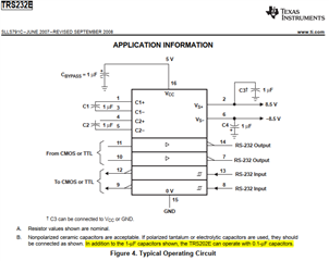
According to the TRS232E datasheet Figure 4, note B, 1uF caps are recommended, but the device can also operate with 0.1uF.
https://www.ti.com/lit/gpn/trs232e

This is not mentioned at all in the MAX232E datasheet, and we're wondering if we should change our BOMs to change to 1uF caps, or if 0.1uF caps would also work with the MAX232E?
I had asked a related question when we replaced the obsolete LMS202ECM/NOPB with the TRS232E and was told the ratio of capacitors was more important than the absolute value of the caps.
Does this reasoning also apply for the MAX232E, even though using 0.1uF caps is not mentioned in the MAX232E datasheet?
We will order some samples for validation, but we just wanted to hear what TI might have to say.
Thanks,
USO
The ratio of the charge pump's capacitors matters only for the ripple. For a fixed (maximum) switching frequency, reducing the size of the flying capacitors increases the output impedance, which might make it impossible to drive the RS-232 load under worst-case conditions. See the Optimizing Output Voltage Ripple for the REG710 application report for details.
0.1 µF capacitors work only if the device can use a high enough switching frequency. The MAX232E datasheet does not allow them, so you should definitely use 1 µF capacitors. (Increase CBYPASS or C3/C4 even more if you want to reduce input or output ripple.)
Hi USO,
Clemens is correct - you shouldn't use the 0.1uF as the charge pump could have issues with driving the load. This device is best operated with 1uF.
Best,
Parker Dodson
Thank you for the quick responses.
We'll update our BOM to use 1uF as recommended. I've learned over the years not to go outside the MFR recommendations ;)
Just to confirm my understanding, it sounds like the switching frequency of the charge pump internal to the MAX232E must be less than the TRS232E, so that's why the TRS232E can work with 0.1uF while the the MAX232E needs 1uF?
If MAX232E and TRS232E are identical, it will probably work for our application with 0.1uF (since we don't have high loading), but it might not meet the guaranteed datasheet specs with higher loading.
That said, we are probably better off changing to at least 1uF to make it more robust.
Thanks for your help.