This thread has been locked.

If you have a related question, please click the "Ask a related question" button in the top right corner. The newly created question will be automatically linked to this question.

TUSB213-Q1: Does TUSB213-Q1 have timing requirements for USB signals when powered on

Part Number: TUSB213-Q1
Other Parts Discussed in Thread: TUSB213, , TUSB216I

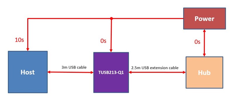
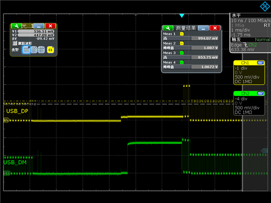
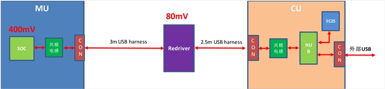
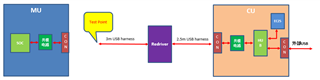
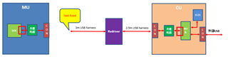
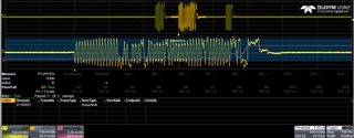
我们设计的框图如下图所示,host会晚于TUSB213约10s上电,我们在实际工作中发现当有TUSB213时有较大概率出现USB会握手失败!请帮忙确认一下TUSB312-Q1在上电时是否有时序要求?谢谢!

Our designed block diagram is shown in the following figure. The host will power on about 10 seconds later than TUSB213. In practical work, we found that there is a high probability of USB handshake failure when TUSB213 is present! Could you please help confirm if there are timing requirements for TUSB312-Q1 during power on? Thank you!

  • 我们今天尝试把TUSB213-Q1短路后,USB就可以通信正常了,从当前现象看还是跟TUSB213-Q1强相关,希望能尽快得到贵司的支持!谢谢!

    We tried to short-circuit TUSB213-Q1 today, and USB can communicate normally. From the current phenomenon, it is still strongly related to TUSB213-Q1. We hope to receive your company's support as soon as possible! Thank you!

  • Hi Yanqing,

    For the TUSB213, the redriver should not be enabled until the power-on ramp has at least settled at 4.4V. Connecting RSTN to a 100nF capacitor to ground should give it the delay it needs.

    What is the status of the CD pin and the ENA_HS pin while the host is attempting handshake? The TUSB213-Q1 only boosts HS signals, which is determines by detecting a HS termination on the signal. If the signal is not high speed, it should detect the signal, but not enable boosting.

    If disabling the device during handshake fixes the issue, then what you may be able to do is hold the RSTN pin of the TUSB213 low via an external GPIO, and once the handshake process is complete, you can allow the RSTN pin to to go back to high, enabling the redriver. This should allow the handshake process to complete while still enabling redriver functionality.

    Thanks,

    Ryan

  • TUSB213-Q1似乎没有CD引脚和ENA_HS引脚!是否还有其TA引脚状态可以测量?

    TUSB213-Q1 seems to have no CD pin and ENA_ HS pin! Is there any TA pin status that can be measured?

    1、如你所说,TUSB213-Q1仅提升HS信号,我们测量到的握手信号如下图所示,第一次握手结束后 TUSB213-Q1似乎开始就提高电压,此时握手就会失败,能否更详细的说明TUSB213是检测到什么信号后开始启用升压(DC Boost is High Level)?

    1、As you mentioned, TUSB213-Q1 only raises the HS signal. The handshake signal we measured is shown in the following figure. After the first handshake, TUSB213-Q1 seems to start raising the voltage, and the handshake will fail. Can you provide more detailed information on what signal TUSB213 detects and starts boosting(DC Boost is High Level)?


    第一次握手结束后的细节波形如下图所示

    The detailed waveform after the first handshake is shown in the following figure

    2、能否提供下TUSB213-Q1的DC BOOST配置为low level和high level时的电压精度分别是多少?

    Can you provide the voltage accuracy of the DC BOOST configuration for TUSB213-Q1 at low and high levels?

    Thank you !

  • Hi Yanqing,

    TUSB213-Q1 seems to have no CD pin and ENA_ HS pin! Is there any TA pin status that can be measured?

    The TUSB213-Q1 does come with CD and ENA_HS pins. These pins are used at start-up to gauge whether SCL is pulled up for I2C and what settings are being used for DC_BOOST. After reset, these pins become status output pins, and can be used to monitor whether a connection is detected and if a HS signal is detected. 

    The pin description for ENA_HS also has more information regarding how it determines if a HS signal is present.

    1、As you mentioned, TUSB213-Q1 only raises the HS signal. The handshake signal we measured is shown in the following figure. After the first handshake, TUSB213-Q1 seems to start raising the voltage, and the handshake will fail. Can you provide more detailed information on what signal TUSB213 detects and starts boosting(DC Boost is High Level)?

    When DC_BOOST is set to high, the odds of the signal disconnecting during handshake increases, as the voltage threshold for handshake can potentially be exceeded. The redriver is seeing a successful handshake via squelch detection occur on the data lanes, which is causing the ENA_HS pin to output confirmation, and the redriver to begin boosting the signal. This boosting could potentially be causing disconnects during handshake if the levels of AC or DC Boost are too high. It may be worth trying lower levels and seeing if this is still present.

    Can you provide the voltage accuracy of the DC BOOST configuration for TUSB213-Q1 at low and high levels?

    At the low, medium, and high levels of DC Boost, the levels of boost are 40mV, 60mV, and 80mV. We do not spec any variation. If you have an NDA with TI and can send me the NDA ID, I can send you HSpice models that have more information.

    Thanks,

    Ryan

  • Hi,sir

    When DC BOOST is configured too high and causes the handshake process to disconnect, does it mean that the host's disconnect or Redriver also has a disconnect mechanism? If it refers to the disconnection mechanism of Redriver, can you provide a disconnection threshold?
    In addition, when the Redriver is not powered on, the measured D1P/D1M and D2P/D2M are connected (only with a resistance of about 3 Ω). Is this normal? If it is normal, can you tell me the principle of boosting? Thank you!

  • Hi Yanqing,

    I am referring to the disconnect threshold of the host. USB2 signals have a certain signal threshold that will cause the host to disconnect the device if the voltage levels of the signal are too high. For the USB2 Spec, this disconnect threshold usually starts at a 525mV differential amplitude.

    In addition, when the Redriver is not powered on, the measured D1P/D1M and D2P/D2M are connected (only with a resistance of about 3 Ω).

    Sorry, I'm not sure what you mean by this. Do you mean that the D1P/M lanes are still connected to D2P/D2M when the device is not powered? This should be the case, as the device signal paths are shorted together within the PCB of the device.

    If this is not what you mean, please clarify, and I will do my best to give you the answer you're looking for!

    Thanks,

    Ryan

  • Hi Ryan

    Thank you !

    1, I understand that the USB disconnect threshold is determined by the host .

    2, What I mean is that when the Redriver is not powered on, there is a resistance of about 3 Ω between D1P and D2P, and there is also a resistance of about 3 Ω between D1M and D2M; There is no short circuit on the PCB, so I suspect there is an internal short circuit in the TUSB213-Q1 chip. If this is the case, I cannot understand how TUSB213-Q1 enhances the USB signal?

    3, NDA  No. :ICMNDADMA_9390

    Can you provide the voltage accuracy of the DC BOOST configuration for TUSB213-Q1 at low and high levels?

    4, We used two extension cables (2.5m) containing Redriver in series for testing. One cable has a drive capacity of 60mV, while the other cable has a drive capacity of 40mV. The theoretical drive capacity for series connection should be 100mV. However, the actual test results are even less than 80mV. What is the reason?

    5,If the drive capacity of the host is 400mV and the DC BOOST configuration of Redriver is 80mV, then the total drive capacity of the USB signal is 480mV. Is this calculation correct?

    Thank you for your support!

  • Hi Yanqing,

    2, What I mean is that when the Redriver is not powered on, there is a resistance of about 3 Ω between D1P and D2P, and there is also a resistance of about 3 Ω between D1M and D2M; There is no short circuit on the PCB, so I suspect there is an internal short circuit in the TUSB213-Q1 chip. If this is the case, I cannot understand how TUSB213-Q1 enhances the USB signal?

    The TUSB213-Q1 shorts the D1M pin to the D2M pin and the D1P pin to the D2P pin internally to keep the data path traces consistent. The TUSB213 and other redrivers in the TUSB21X family of redrivers boosts the signals that come through it by passively adding current to the signal that passes through or under it. This allows the device to have minimal impact on the amount of jitter and noise added to the signal while still boosting the signal.

    3, NDA  No. :ICMNDADMA_9390

    Can you provide the voltage accuracy of the DC BOOST configuration for TUSB213-Q1 at low and high levels?

    I have sent you a friend request, if you accept it, I can send you some HSpice models which have more information.

    4, We used two extension cables (2.5m) containing Redriver in series for testing. One cable has a drive capacity of 60mV, while the other cable has a drive capacity of 40mV. The theoretical drive capacity for series connection should be 100mV. However, the actual test results are even less than 80mV. What is the reason?

    The drive capacity describes the amount of voltage being added to the levels of VHigh and VLow as it passes though the redriver. That means that right as the signal comes out of the redriver, there should be an additional 60mV being added to VHigh and VLow. However, as the signal goes though those 2.5m cables, the signal will gradually begin to lose that boost, with the longer the cable, the less of a boost you will see at the end of the cable. If you are measuring the signal at the end of those 2.5m cables, then it is likely that signal has deteriorated enough to not retain the full boost added by the redrivers.

    5,If the drive capacity of the host is 400mV and the DC BOOST configuration of Redriver is 80mV, then the total drive capacity of the USB signal is 480mV. Is this calculation correct?

    This depends on where the redriver is located. If located at or near to the host, then yes, you could consider the driving capability as being 480mV. Otherwise, if the redriver is located at the device, then the driving capability of the device would be less than that.

    Please let me know if you have any other questions.

    Thanks,

    Ryan

  • Hi Ryan

    2、I understand what you mean, is this signal enhancement bidirectional? Will Redriver detect the magnitude of USB signal amplitude? If the amplitude of the USB signal is not detected, it means that no matter how large the input USB signal is, the set improvement value will be increased?

    3,What software needs to be used to open. sp in the HSpice model? As mentioned above, the way TUSB213 enhances USB signals is achieved by passively injecting current into the DM/DP. So, I understand that the accuracy of this driving capability improvement is related to the injection current accuracy, injection current magnitude, and external termination resistance? I understand that the accuracy of DC BOOST is equal to the deviation of the injection current multiplied by the external termination resistance. Is my understanding correct?

    5,The position of the Redriver is in the middle of the wiring harness, as shown in the figure. Is the total drive capacity of the USB signal 480mV correct?

  • Hi Yanqing,

    2、I understand what you mean, is this signal enhancement bidirectional? Will Redriver detect the magnitude of USB signal amplitude? If the amplitude of the USB signal is not detected, it means that no matter how large the input USB signal is, the set improvement value will be increased?

    The signal enhancement is bidirectional, yes, meaning that the signal will be boosted as it goes through the redriver, regardless of the direction. Additionally, like you suggested, the redriver does not monitor the amplitude of the signal as it goes through the redriver, it isonly paying attention to whether a connection is detected and if the signal is high-speed for determining if the signal should be boosted or not.

    3,What software needs to be used to open. sp in the HSpice model? As mentioned above, the way TUSB213 enhances USB signals is achieved by passively injecting current into the DM/DP. So, I understand that the accuracy of this driving capability improvement is related to the injection current accuracy, injection current magnitude, and external termination resistance? I understand that the accuracy of DC BOOST is equal to the deviation of the injection current multiplied by the external termination resistance. Is my understanding correct?

    There is no TI-standard software for these files, you may try using something like Allegro, or ADS. Your local FAE, I believe it's Jiaqi, should have a picture for DC Boost from the HSpice models. You may ask them. As for the injection current and similar processes, I am not able to say more, as this information if proprietary to TI, and cannot be shared externally.

    5,The position of the Redriver is in the middle of the wiring harness, as shown in the figure. Is the total drive capacity of the USB signal 480mV

    No, in this case, the total drive capacity would be less than 480mV, as the redriver is spaced 2.5-3 meters from the host.

    Please let me know if you have any other questions.

    Thanks,

    Ryan

  • Hi Ryan

    Thank you for your reply!

    2. I guess TUSB213 determines whether it is a high-speed signal by detecting the DC level of the USB signal (the high-speed signal level is about 400mV), is this guess correct? If not, can you tell me the principle?

    3. Ok, I will ask jiaqi for help.

    5. Do you think the reason why the total driving capacity is less than 480mV is because there is a line loss?

    6. Should DCR be considered when TUSB213 is working? (As mentioned above, when TUSB213 is not powered on, there will be about 3Ω resistance between D1M and D2M. Does this resistance still exist when powered on?)

    Thanks !

  • Hi Ryan

    Thank you for your reply!

    2. I guess TUSB213 determines whether it is a high-speed signal by detecting the DC level of the USB signal (the high-speed signal level is about 400mV), is this guess correct? If not, can you tell me the theory?

    3. Ok, I will ask jiaqi for help.

    5. Do you think the reason why the total driving capacity is less than 480mV is because there is a line loss?

    6. Should DCR be considered when TUSB213 is working? (As mentioned above, when TUSB213 is not powered on, there will be about 3Ω resistance between D1M and D2M. Does this resistance still exist when powered on?)

    7. I tested the USB2.0 electrical compatibility test (EL_21, EL_22, EL_25) when the hub upstream port is with Redriver, and found that the test failed; After removing the Redriver, the test passed. What is the reason?

    Thanks !

  • Hi Yanqing,

    2. I guess TUSB213 determines whether it is a high-speed signal by detecting the DC level of the USB signal (the high-speed signal level is about 400mV), is this guess correct? If not, can you tell me the theory?

    The TUSB213-Q1 uses two means of determining whether or not there is a high-speed signal. It will either detect a USB-IF test fixture being connected with USB TEST_PACKETS being sent, or will use squelch detection following a USB reset completed with a successful HS Handshake.

    5. Do you think the reason why the total driving capacity is less than 480mV is because there is a line loss?

    Yes, that is correct. Due to the 2.5+ meters of cable between the host/device board and the redriver, the driving capacity of the signal once it reaches the redriver will be less than 400mV due to a variety of causes, such as insertion loss, ISI jitter, noise, or signal transmission. This means that once the signal is boosted, it will not be boosted up to 480mV, but rather whatever the driving force of the signal is once it reaches the redriver.

    6. Should DCR be considered when TUSB213 is working? (As mentioned above, when TUSB213 is not powered on, there will be about 3Ω resistance between D1M and D2M. Does this resistance still exist when powered on?)

    This value could be considered typical for the TUSB213, but TI does not spec for this parameter, as we have not completed any testing to determine what the value of the DCR is. I cannot confirm whether this value is still present during power on or not either.

    7. I tested the USB2.0 electrical compatibility test (EL_21, EL_22, EL_25) when the hub upstream port is with Redriver, and found that the test failed; After removing the Redriver, the test passed. What is the reason?

    Is this being done with redriver removed? Or redriver being set to RSTN? If removed, I would appreciate it if you could try this test again, but keeping the TUSB213-Q1 held in reset via the RSTN pin.

    Please let me know if you have any questions or if anything else comes up.

    Thanks,

    Ryan

  • Hi Ryan

    Thank you for your reply!

    2,Our Test found that redriver can also improve the amplitude of USB signal in Test J/K mode, and the difference between 60mV and 40mV when redriver is configured is about 20mV.
    Because Test J/K sends continuous high level on USB D+/D-, I would like to confirm with you whether there is any problem with this test. Is this result credible?

    7,This is the waveform tested with a Redriver (using a 2.5m extension cable), which is in normal working mode. The test waveform at this time is shown above.From the waveform perspective, Redriver seems to have affected the transmission of the test waveform.

    When keeping the RSTN pin of the redriver low, USB cannot enumerate and therefore cannot be tested.

    The waveform of the Redriver test removed is shown in the following figure, and the result is pass!

    Thanks

  • Hi Yanqing,

    2,Our Test found that redriver can also improve the amplitude of USB signal in Test J/K mode, and the difference between 60mV and 40mV when redriver is configured is about 20mV.
    Because Test J/K sends continuous high level on USB D+/D-, I would like to confirm with you whether there is any problem with this test. Is this result credible?

    Is this before or after the High-speed signal handshake? If it is after the HS handshake is completed and reset, then this seems correct to me. If the device is not disconnecting or having any issues, then I dont see any issue with this, and if you are noticing a difference in voltage levels when measuring with different settings, then that would be a good indicator of the settings changing and boosting the signal.

    7,This is the waveform tested with a Redriver (using a 2.5m extension cable), which is in normal working mode. The test waveform at this time is shown above.From the waveform perspective, Redriver seems to have affected the transmission of the test waveform.

    Where are these signals being measured in reference to the block diagram? Additionally, what settings are being used? Is DC Boost at 80mV still? It seems odd to me that the redriver is having this much of an effect on the packets.

    Please let me know.

    Thanks,

    Ryan

  • Hi Ryan

    Thank you for your reply!

    2. This was tested after the HS handshake was completed and reset! This can be used as an indicator for signal enhancement, I understand!

    7. The testing location is shown in the block diagram, which tests the data packet parameters of the hub upstream port (EL_21, EL_22, EL_25). During the testing, a 40mV boost was used.

  • Hi Yanqing,

    7.) Would it be possible to test at a few different points as well, such as those i have marked by a red square in the block diagram? I would like to see how these signals look closer to the termination, as well as how the signals look leaving the device and arriving at the hub.

    Please let me know.

    Thanks,

    Ryan

  • Hi Ryan

    Thank you for your reply!

    7,As long as Redriver is not included, the test results of the two test points you pointed out are both passed!
    When testing with Redriver, the host (PC) can normally enumerate USB ports. From the test waveform, it seems that the host did not receive the test waveform after passing through Redriver, so there is no response from the hub!

    Has TI ever done this test? Can you share your test results?

    thanks

  • Hi Yanqing,

    I did some testing on my side, and from what I can tell, the TUSB213 should be able to complete testing from either the host or device side, with there being a one meter cable between the host and the redriver, and another one meter cable between the redriver and the device.

    TUSB213Host_DeviceTest.zip

    If possible, would you be able to send over the schematic surrounding the TUSB213? I would like to see if there is potentially some issue there.

    Additionally, do you have any EVMs for any other TUSB21XX redrivers, I.E the TUSB216I? If so, I would appreciate it if you could try using those and seeing if they replicate this issue, or if it something specific with the TUSB213.

    Please let me know.

    Thanks,

    Ryan

  • Hi Ryan

    Thank you for your reply!

    You may have misunderstood, we have only found that testing 'Packet Parameters' cannot pass! All other tests are normal (including eye maps, Test J, Test K, etc.)! We don't have any other EVM's to use! Can you also test the 'Packet Parameters' to see if it's the same as my situation? Thank you!

  • Hi Yanqing,

    Ah, I see, got it.

    I went into the lab and ran those tests, specifically EL_21 and EL_25, and from what I could tell on my side, with DC Boost set to 1, and the same distance set up as yesterday, it seemed like these tests were still able to be completed successfully from my side (Indicated by Q1: Pass/Fail.)

    I understand about have no other EVM's, we can focus on the TUSB213 then. If you could send your schematic, that would be good for us to review as well, just to be safe. We are friends on E2E, so if you wish to keep it off the public thread, you can send me a private message with it there.

    Please let me know.

    Thanks,

    Ryan

  • Hi Yanqing,

    "From our testing, it seems that the reason for the test failure was that Redriver did not correctly recognize the HS signal when enumerating USB. I tried to turn off the power of the Redriver and turn it back on after enumerating USB devices, so that the Redriver can correctly recognize the HS signal! But I cannot understand the reason why Redriver cannot recognize HS signals during direct testing. What is your opinion?"

    So, when the redriver is enabled during enumeration, the redriver does not recognize the HS signals after the HS handshake? Or do you mean something different?

    When you disable the redriver during enumeration and then re-enable it, does this fix the issue? Does the redriver function correctly after that?

    Thanks,

    Ryan