This thread has been locked.
If you have a related question, please click the "Ask a related question" button in the top right corner. The newly created question will be automatically linked to this question.
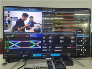
We used 12G UHD-SDI dual input driver ,Part number: LMH1218RTWT,-40℃to+85℃,QFN24. when we are debugging , the following problems occurred: We used LMH1218 to drive sdi, 4kp50 p60 can not detect the signal, 4kp30 when the amplitude is not enough, the signal can not be detected by Ophthalmograph analyzer, but the image can be seen by the monitor. How to solve this problem?
Greetings Shaojun,
There are a few places where this error could be coming from, to be able to help you, you should install SigCon Architect using this link: SigCon Architect V2.0.0.8 WRTE
Set up the LMH1218 to see the high level page, please send a screenshot like this when you have it set up:
On the low level page, please send us your config file because we want to see the registers you use.
best,
Nick
hi,i am not use spi or i2c program the chip i just power on the chip,so i think the chip use the default config file.
Hi,
Thank you for the information. The LMH128 requires an initialization set up as specified in table 10 on page 47 in the datasheet shown in the screen shot below:
There are two methods of accessing the LMH1218 registers:
Serial management bus (SMBus)
Serial parallel interface (SPI)
Please refer to the programming guide sections 1 to 1.1 for instructions on choosing the protocol and for more register tables. The LMH1218 requires register initialization and cannot be operated in pin mode.
Alternatively, if you are interested in operating the part in pin mode - in addition to the SPI or SMBUS interface - then please consider LMH1228. Link to this part's data sheet: LMH1228
Best,
Nick
//4kp50 reg[F0]==1F reg[F1]==0 reg[0]==0 reg[4]==0 reg[6]==0 reg[FF]==4 reg[0]==0 reg[1]==2 reg[2]==5C reg[54]==80 reg[56]==0 reg[3]==80 reg[D]==0 reg[13]==90 reg[14]==0 reg[15]==0 reg[2D]==8 reg[31]==0 reg[3A]==0 reg[40]==0 reg[41]==40 reg[42]==80 reg[43]==50 reg[44]==C0 reg[45]==90 reg[46]==54 reg[47]==A0 reg[48]==B0 reg[49]==95 reg[4A]==69 reg[4B]==D5 reg[4C]==99 reg[4D]==A5 reg[4E]==E6 reg[4F]==F9 reg[52]==80 reg[55]==2 reg[9]==0 reg[A]==50 reg[C]==8 reg[11]==E0 reg[16]==25 reg[23]==40 reg[24]==0 reg[25]==0 reg[26]==0 reg[27]==0 reg[28]==0 reg[29]==60 reg[2A]==30 reg[2C]==32 reg[2F]==6 reg[32]==11 reg[3E]==0 reg[69]==A reg[6A]==0 reg[A0]==1F reg[1C]==98 reg[1E]==29 reg[1F]==10 reg[80]==20 reg[84]==4 reg[85]==0 //4kp60 reg[F0]==1F reg[F1]==0 reg[0]==0 reg[4]==0 reg[6]==0 reg[FF]==4 reg[0]==0 reg[1]==2 reg[2]==5C reg[54]==80 reg[56]==0 reg[3]==80 reg[D]==0 reg[13]==90 reg[14]==0 reg[15]==0 reg[2D]==8 reg[31]==0 reg[3A]==0 reg[40]==0 reg[41]==40 reg[42]==80 reg[43]==50 reg[44]==C0 reg[45]==90 reg[46]==54 reg[47]==A0 reg[48]==B0 reg[49]==95 reg[4A]==69 reg[4B]==D5 reg[4C]==99 reg[4D]==A5 reg[4E]==E6 reg[4F]==F9 reg[52]==80 reg[55]==2 reg[9]==0 reg[A]==50 reg[C]==8 reg[11]==E0 reg[16]==25 reg[23]==40 reg[24]==0 reg[25]==0 reg[26]==0 reg[27]==0 reg[28]==0 reg[29]==60 reg[2A]==30 reg[2C]==32 reg[2F]==6 reg[32]==11 reg[3E]==0 reg[69]==A reg[6A]==0 reg[A0]==1F reg[1C]==98 reg[1E]==29 reg[1F]==10 reg[80]==20 reg[84]==4 reg[85]==0 //4kp30 reg[F0]==1F reg[F1]==0 reg[0]==0 reg[4]==0 reg[6]==0 reg[FF]==4 reg[0]==0 reg[1]==2 reg[2]==5C reg[54]==80 reg[56]==0 reg[3]==80 reg[D]==0 reg[13]==90 reg[14]==0 reg[15]==0 reg[2D]==8 reg[31]==0 reg[3A]==0 reg[40]==0 reg[41]==40 reg[42]==80 reg[43]==50 reg[44]==C0 reg[45]==90 reg[46]==54 reg[47]==A0 reg[48]==B0 reg[49]==95 reg[4A]==69 reg[4B]==D5 reg[4C]==99 reg[4D]==A5 reg[4E]==E6 reg[4F]==F9 reg[52]==80 reg[55]==2 reg[9]==0 reg[A]==50 reg[C]==8 reg[11]==E0 reg[16]==25 reg[23]==40 reg[24]==0 reg[25]==0 reg[26]==0 reg[27]==0 reg[28]==0 reg[29]==60 reg[2A]==30 reg[2C]==32 reg[2F]==6 reg[32]==11 reg[3E]==0 reg[69]==A reg[6A]==0 reg[A0]==1F reg[1C]==98 reg[1E]==29 reg[1F]==10 reg[80]==20 reg[84]==4 reg[85]==0 //1080p60 reg[F0]==1F reg[F1]==0 reg[0]==0 reg[4]==0 reg[6]==0 reg[FF]==4 reg[0]==0 reg[1]==2 reg[2]==5C reg[54]==80 reg[56]==0 reg[3]==80 reg[D]==0 reg[13]==90 reg[14]==0 reg[15]==0 reg[2D]==8 reg[31]==0 reg[3A]==0 reg[40]==0 reg[41]==40 reg[42]==80 reg[43]==50 reg[44]==C0 reg[45]==90 reg[46]==54 reg[47]==A0 reg[48]==B0 reg[49]==95 reg[4A]==69 reg[4B]==D5 reg[4C]==99 reg[4D]==A5 reg[4E]==E6 reg[4F]==F9 reg[52]==80 reg[55]==2 reg[9]==0 reg[A]==50 reg[C]==8 reg[11]==E0 reg[16]==25 reg[23]==40 reg[24]==0 reg[25]==0 reg[26]==0 reg[27]==0 reg[28]==0 reg[29]==60 reg[2A]==30 reg[2C]==32 reg[2F]==6 reg[32]==11 reg[3E]==0 reg[69]==A reg[6A]==0 reg[A0]==1F reg[1C]==98 reg[1E]==29 reg[1F]==10 reg[80]==20 reg[84]==4 reg[85]==0 //1080p30 reg[F0]==1F reg[F1]==0 reg[0]==0 reg[4]==0 reg[6]==0 reg[FF]==4 reg[0]==0 reg[1]==2 reg[2]==5C reg[54]==80 reg[56]==0 reg[3]==80 reg[D]==0 reg[13]==90 reg[14]==0 reg[15]==0 reg[2D]==8 reg[31]==0 reg[3A]==0 reg[40]==0 reg[41]==40 reg[42]==80 reg[43]==50 reg[44]==C0 reg[45]==90 reg[46]==54 reg[47]==A0 reg[48]==B0 reg[49]==95 reg[4A]==69 reg[4B]==D5 reg[4C]==99 reg[4D]==A5 reg[4E]==E6 reg[4F]==F9 reg[52]==80 reg[55]==2 reg[9]==0 reg[A]==50 reg[C]==8 reg[11]==E0 reg[16]==25 reg[23]==40 reg[24]==0 reg[25]==0 reg[26]==0 reg[27]==0 reg[28]==0 reg[29]==60 reg[2A]==30 reg[2C]==32 reg[2F]==6 reg[32]==11 reg[3E]==0 reg[69]==A reg[6A]==0 reg[A0]==1F reg[1C]==98 reg[1E]==29 reg[1F]==10 reg[80]==20 reg[84]==4 reg[85]==0
Hi Shaojun,
After checking the registers, I see that the LMH1218's CDR is locked. Can you send your block diagram? And another thing we suggest is to use USB2ANY and Sigcon Architect to be able to view the register high level page.
In this picture of the high level page you should see the CDR as locked in green. With USB2ANY the registers are more easily accessed. Here is the USB2ANY link and the Sigcon architect application is linked above.
Best,
Nick
sorry, i have no usb2any, i use fpga to program your chip; first i can read the right chip id 0x60;but after initial the register ,i read the id wrong. The below is my code:
void read_spi_ti(u8 reg) { u8 WriteBuffer[3];//={0xff,0xf1,0xff}; u8 ReadBuffer[3];//={0x00,0x00,0x00}; WriteBuffer[0] = 0xff; WriteBuffer[1] = reg; WriteBuffer[2] = 0xff; XSpi_Transfer(&SpiInstance_ti, WriteBuffer, NULL, 3); WriteBuffer[0] = 0xff; WriteBuffer[1] = 0xff; WriteBuffer[2] = 0xff; XSpi_Transfer(&SpiInstance_ti, WriteBuffer, ReadBuffer, 3); xil_printf("reg[%x]==%x\r\n", (u8)((u8)(ReadBuffer[0] << 1)+(ReadBuffer[1] >> 7)),(u8)((u8)(ReadBuffer[1] << 1)+(ReadBuffer[2] >> 7))); } void write_spi_ti(u8 reg,u8 data) { u8 WriteBuffer[3];//={0xff,0xf1,0xff}; WriteBuffer[0] = 0xfe; WriteBuffer[1] = reg; WriteBuffer[2] = data; XSpi_Transfer(&SpiInstance_ti, WriteBuffer, NULL, 3); } main () { read_spi_ti(0xf1); usleep(10); write_spi_ti(0xff,0x04); usleep(10); write_spi_ti(0x16,0x25); usleep(10); write_spi_ti(0x3e,0x00); usleep(10); write_spi_ti(0x55,0x02); usleep(10); write_spi_ti(0x6a,0x00); usleep(10); write_spi_ti(0x03,0x00); usleep(10); write_spi_ti(0x0a,0x5c); usleep(10); write_spi_ti(0x0a,0x50); usleep(10); read_spi_ti(0xf1); usleep(10); read_spi_ti(0xf1); usleep(10); read_spi_ti(0xf1); usleep(10); }
Hi Shaojun,
The addresses and registers you update in the main file are in concordance with the programming guide. The device ID does not change unless its register is updated in the code or by the FPGA.
Can I have more information about the FPGA and code? What does the function XSpi_Transfer() looks like? And what does this line of code do?
(u8)((u8)(ReadBuffer[0] << 1)+(ReadBuffer[1] >> 7)),(u8)((u8)(ReadBuffer[1] << 1)+(ReadBuffer[2] >> 7)))
Have you checked whether the outputs are correct? Note that out0 has a differential impedance of 75 ohms and out1 has a differential impedance of 100 ohms.
Best,
Nick
Hi Nick,
(u8)((u8)(ReadBuffer[0] << 1)+(ReadBuffer[1] >> 7)) is the address of the register; (u8)((u8)(ReadBuffer[1] << 1)+(ReadBuffer[2] >> 7))) is the read data of the register; i get this from figure17 (https://www.ti.com/lit/ds/symlink/lmh1218.pdf?ts=1695623873986&ref_url=https%253A%252F%252Fwww.ti.com%252Fproduct%252FLMH1218);
XSpi_Transfer() is xilinx's spi transform source code, you can get here "">github.com/.../xspi.c"
Hi Shaojun,
The code looks correct.
Please hook up a scope and a signal generator to the device before initialization and see if the device is outputting data. Then, try to see if you can output data after initialization. Check if the device ID is changing.
Best,
Nick
Hi Nick, after power on the chip,before initialization i can read the correct device id,but ater initialization ,the device id was wrong;Do you have a reference with xilinx fpga?Can you send some more reference to us? Thank you.
Hi Shaojun,
We do not have any reference materials with Xilinx FPGAs for your data rate. You may be able to find information from AMD.
We are going to set up your situation in the lab using the LMH1218 to see if we can get the results you have. I'll report back to you tomorrow morning, in the meantime please send me your block diagram, and refer to the previous messages in this thread to guide you in your next steps.
Best,
Nick
Hi Shaojun,
After reviewing the schematic with my colleagues, we've come to the conclusion that it you would benefit from testing with the LMH1218 EVM, linked here: https://www.ti.com/tool/LMH1218EVM
We see in the lab that changing the CTLE equalization register written to address 0x03 is important for signal optimization. The signal that leaves the LMH1218 is subject to parasitics along your transmission line which may be causing your problem.
Furthermore, it's not possible to update the Device ID, which is why we believe that your SPI read is not functioning correctly. The USB2ANY and the EVMS would allow you to update the CTLE settings and initialize your device in a more simple manner. That is why moving forward we suggest developing within those frameworks.
Best,
Nick
hi nick:
I think it is my fault,when read the device id,i should first write the data 0x00 to register 0xff. After done this, i can read the write device id.
I write value 0x80 (0x90,0x10) to register 0x03,the output0's amplitude is not change.
I try to change the value of register 0x80,the optput0's amplitude bigger(up to 500mv),but the video flash, sometimes ,i lost the video.
What i will try next? I ask the FAE,he alse have no lmh1218 evm.
Hi Shaojun,
Good catch in noticing that you need to write 0x00 to 0xff. Please refer to the following image for your problem.
There are two ways to change the output at output 0, by changing register 0x03 and changing register 0x80:
When you write to 0x03 you change the vertical eye opening( VEO). For example, in the image above I wrote 0x80 to 0x03 and got a VEO of 450mv, but if I were to write 0x77 to 0x03 it would a VEO(mV) of 312.5mv.
Please refer to the pdf below with the LMH1218 programming guide, register 0x80 drv_0_sel_vod[3:0] is typically 42 mV per step, if you want to reduce the output0 you can change the register 0x80 to "Nominal -10%" by setting 0x80 to 0x36. Please play around with the register settings some more to optimize your device for your application. You are on the right track.
hi Nick,
We buy a USB2ANY, and connect spi bus(4-wire + 3.3v+gnd) to our mainboard. From the GUI(Sigcom),I only find the i2c mode,how can i change to spi mode?
Hi Shaojun,
Table 2 in this pdf has more information on the USB2ANY pinout. Check all the slave addresses when you are trying to connect.
-Nick
Hi Nick,
The sicon software you send to me only have one (i2c buf)option, not include spi bus option; how can i change to spi mode via SIGcon software?
Hi Shaojun,
The software should detect the device through USB2ANY if the mode is SPI or SMBUS. There is nothing in the software which you have to click to turn on SPI mode. The most common reason which the USB2ANY does not detect is because the address is incorrect.
Is the device in SPI mode? Is the enable pin pulled high with a 1kohm resistor?
Please review this table to see what I mean.
If this isn't the problem, please check the address is correct.
Best,
Nick
I am sure the device is in spi mode; what is the address of the spi mode? The address of i2c is 0x1a.
Which pin of USB2Any (j4) detect the lmh1218 is spi mode or i2c mode?
From the schematic of lmh1218 evm(figure14), i can not find the detect mode pin ,just spi 4 wire ,power and gnd.
Hi Shaojun,
I'm sorry to tell you this so late, but I found out that the USB2ANY does not work with LMH devices in Sigcon Architect. It is only possible to use Sigcon Architect for SDI devices with SMBUS or I2C.
Let me know if you would like more help securing the LMH1218 EVM, which would work with Sigcon architect. If not, I'm going to close this thread because it has been going on for a while.
Best,
Nick
Hi Team,
Could you suggest a solution since the USB2ANY unavailable above mentioned? Thanks.
William
Hi William,
Allison coordinated with you via email. We have one LMH1218EVM in stock.
Best,
Nick
Hi Nick,
Yes, I will suggest customer test on the EVM, and post you the update via this thread.
Thanks.
William