This thread has been locked.

If you have a related question, please click the "Ask a related question" button in the top right corner. The newly created question will be automatically linked to this question.

TCAN332G: TCAN332G and ESP32 failure

Part Number: TCAN332G
Other Parts Discussed in Thread: TCAN332, ALLIGATOR,

I made a custom pcb with a ESP32 WROOM and a TCAN332GDR. It is connected to a CAN device, with no termination, with a twisted pair of 1m. This does not work.

I have the TCAN-EVM and an off the shelf ESP32 dev board, it communicates with the CAN device at 500khz. This setup works.

Both are using the same software, a simple test program.

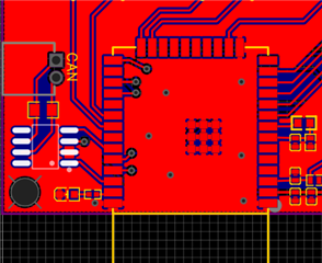
My custom pcb is shown below. The 120ohm resistor is not connected. I crammed a 100ohm resistor into the connector but no improvement. I set the device to use 125khz, but still no luck with my custom pcb.

I have a cheap usb logic analyzer that shows my CANBUS packet, but no response from the other CAN device. I do see the response when using the evm/dev board. (I do not know enough about CAN to say that there is absolutely nothing from the CAN device). I do not have anything that will show me the analog signal on the bus.

Both setups will transmit forever, (with or w/o the other device connected). This tells me that both setups are capable of reading their own transmissions.

My board does not have the 4.7uf capacitor between VCC and GND that I see on the TCAN-EVM, but ...

I then removed the TCAN332 chip and connected the TCAN EVM with some alligator clip wires to the custom pcb, and it still does not work (RX, TX, VCC, and GND).

Given this, I expected to find some pullups or caps on the gpio21/22 (rx/tx) on the dev board, but there is no such thing. The traces for 21/23 are short and bare.

I find no documentation indicating there is a difference between the ESP32-WROOM-32E (mine) and 32D (dev board) that would affect this.

The voltage on the dev board was 3.33 and the voltage on the custom board, which is powered by the ESP-PROG via usb was 3.28.

(https://oshwlab.com/cost.co/esp32_dev here is a virtually identical design from someone else, the only difference is that he's using the SN65HVD, and I am using the TCAN332 )

Can someone give me some ideas? 

EDIT: Two of my boards are able to talk to each other.

Additionally, I put my board, and the esp32dev/TCAN EVM setup, and the CAN device all on the bus (this is really a star, but only 1 leg is 1m). Only the dev/evm setup is able to transmit and receive from the CAN device. My board hears nothing, and the dev/evm setup shows nothing when my board sends.

Finally I put another of my boards onto the star and it transmitted a packet that its twin hears, but not the dev/evm setup, but then it freezes. If I reboot that board, it delivers another to its twin. I think it freezes when it does not hear itself on the bus.

I'm going nuts.

  • This sounds as if the TCAN332G works OK, and there is a problem with the software (configuration) running on your ESP. It might be a different clock speed.

  • Hi John,

    Thanks for sharing your question on E2E. I can definitely understand how frustrating it is when things seem so close to working like it seems to be here. 

    I agree with Clemens that this is likely a software configuration mismatch as it sounds like your custom boards are able to communicate with each other. If this was a hardware issue, I would expect that these boards would not be able to communicate with anything at all. 

    The fact that the boards "freeze" after attempting to communicate is also telling that this may be a configuration issue. CAN controllers handle all of the protocol aspects of CAN communication and are responsible for identifying and reacting to errors that occur in the system. One of these responsibilities is to remove itself from the bus (go "bus off")if it suspects that it is the culprit of several transmit errors. Similarly, if the node identifies several receive errors in a row, it will stop sending error frames as to not disrupt other nodes that may be capable of communicating without issue. 

    Please check that all of the CAN controllers are configured with the same data rate as the rest of the bus ensuring that the speed of the local reference clock is taken into account (if the clock speed is 2x the other boards clocks, the bit time configuration will need to be 1/2 the total time quanta). Also ensure that none of the nodes are configured to send CAN frames with the same ID as another node. The CAN protocol uses the ID of the CAN frame to determine message priority. If two nodes transmit the same ID, they will collide as it is not possible to determine which message has priority to be transmitted first. 

    Lastly, it is incredibly helpful to look at analog behavior when debugging transceiver-related issues. I understand that oscilloscopes can be quite cost-prohibitive, but there are some cost effective options that still give good-enough resolution to do some effective debug. I personally use an Analog Discovery 2 for my at-home setup which has two scope channels. 
    https://digilent.com/reference/test-and-measurement/analog-discovery-2/start 

    Let me know if you have any more questions and keep us updated on your debug process. 

    Regards,
    Eric Schott 

  • Thanks for the feedback Clemens and Eric.

    The software is identical. I pull the usb cord from my board (with esp-prog) and plug it into the dev/evm setup and download and run. My simple test case has 1 of either my board or the dev/evm setup, and just 1 other CAN device. So, if the dev/evm can transmit a query to the device and get a response forever, there should be no reason why my board is no different. I see the query packet on the logic analyzer in both situations, but mine gets no response from the other CAN device.

    The only clocks are internal to the esp32.

    I am poor at the analog part of circuit design. I mean I don't really understand when to place, and how to size a capacitor, for example. The only difference I see between the EVM board and my TCAN332 is a 4.7uF cap between vcc+gnd. I figure that cap is there to smooth out the power as the transceiver bangs away at 500khz. But, then removing the TCAN and instead wiring to the evm still failed. (Why doesn't the TCAN332 have an internal capacitor on its VCC anyway?). 

    So maybe my board just cannot get the power to the transceiver with enough reserve? The ground path is rather circuitous from the TCAN, but we're talking a handful of cm to the usb. My VCC trace is .25mm. The TCAN says max Icc is 60ma, which seems large. Both setups are getting max .5A@5V from the usb port.

    I figured that the combo of esp32 and TCAN332 would not be very picky with respect to the analog part of the circuit. I mean, if my traces are short, and there's no other high frequency stuff on the board, it should be fine. Am I wrong?

    I'll try my board with the bigger power supply and get an o-scope.

  • I finally noticed that the timescale was different between mine and the one that works. This means that the esp32-wroom-32D and esp32-wroom-32E are different. The notice states that the E has a lower minimum CAN frequency, but I think that is a mistake. I think they mean to state that they shifted the whole set of frequencies down, so that the same setting on D produces a lower frequency on E.

    The software library I used takes the frequency as an argument (e.g. 500000) and does a lookup to stuff the correct value into the TWAI thing on the ESP32. That table lookup needs to know whether it is a D or E version.

    UGGGGH!

    Hopefully this might save someone some frustration.