This thread has been locked.

If you have a related question, please click the "Ask a related question" button in the top right corner. The newly created question will be automatically linked to this question.

SN65HVD230: 252FSN65HVD230

Part Number: SN65HVD230

Hi i an currently designing an PCB for orange pi 5 plus for our energy storage containers.

For your information I am not an professional circuit designer but very enthusiastic and learns a lot each day.

this pcb will be for our communication to the inverter (CAN and rs485 modbus) and also isoSPI.

I got 5v and 3,3v to chose but the GPIOS can only handle 3.3v

wh got a lot of emc interference at 3Mhz.

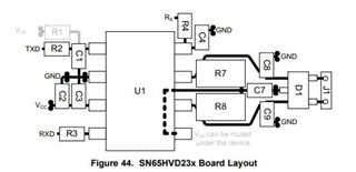
the thing I am asking is how I should set up this ic: 252FSN65HVD230, I’m talking of what resistors and capacitors do I really need? On the data specification it is a lot of components. Should I use all of this in the sample layout?

also I need to implement UART to rs485 

what ic do you reccomend for this purpose? 

best regards

Sebastian

  • Sebastian,

    I'd recommend looking at pages 33 and 34 of the datasheet for part placing and layout recommendations. 

    In this example, C2, C3, R7, R8, and C7 are recommended as a bare minimum. C2 and C3 are needed to decouple and filter the power input, R7 and R8 are needed for termination of the CAN signals on the bus, and C7 in combination with R7 and R8 is a low-pass filter for both CANH and CANL. C2 and C3 can be 4.7uF and 100nF, respectively. R7 and R8 should be 60 ohms, and C7 can range from 4.7nF to 100nF.

    Can you also share waveforms of the CANH and CANL signals?

    For UART to RS485, I'd recommend looking on TI.com and searching through our RS-485 transceivers. If you don't have any other requirements for the UART to RS485, or if you don't even know what features are available, our selection tool on TI.com can help guide you.

    Regards,

    Eric Hackett 

  • Can you also share waveforms of the CANH and CANL signals?

    I will send this to you when I have the waveforms (we have lack of some equipment for now)

    Thank you Eric for your fast reply Slight smile

    good explanation to!

    I really appreciate you taking time to answer my thoughts Slight smile

    This is the setup I understood from what you told me and some questions

    C2 4,7uF

    C3 100nF

    R7,R8 60ohms, whould the other devices con r Ted on the same CAN L,H need this to or is it ok to just have here?

    C7 4,7nF-100nF, how can I tell what to chose? Or can I calculate this in some way?

    About the UART>rs485 

    I found this ic: https://www.ti.com/lit/ds/symlink/thvd1449v.pdf?ts=1698558040551&ref_url=https%253A%252F%252Fwww.ti.com%252Fproduct%252FTHVD1449V

    this ic has built in tvs diodes for protection and seems very good, 


    from this layout I got this questions.

    1) 100nF-220nF how can I know which value to chose?

    3) 1k-10k same here, how can I decide this? 

    Is the Vio the bus voltage? Could not really understand s this from the data sheet

    what do I need to do if I need 5v rs-485 bus but the orange pi can only handle 3.3v?


    Best regards

    Sebastian 

  • Sebastian,

    R7,R8 60ohms, whould the other devices con r Ted on the same CAN L,H need this to or is it ok to just have here?

    C7 4,7nF-100nF, how can I tell what to chose? Or can I calculate this in some way?

    For C7, it will depend on the cutoff frequency for the low-pass common-mode filter, but in general I would recommend 4.7nF.

    I'm not sure exactly what your question about R7 and R8 is, can you please try and ask again?

    from this layout I got this questions.

    1) 100nF-220nF how can I know which value to chose?

    3) 1k-10k same here, how can I decide this? 

    Is the Vio the bus voltage? Could not really understand s this from the data sheet

    what do I need to do if I need 5v rs-485 bus but the orange pi can only handle 3.3v?

    For the decoupling capacitors, since you're really just trying to filter out high-frequency noise, the difference between 100nF-220nF from an application level is minimal. It will just affect the frequency at which the noise begins to attenuate. I would recommend 100nF since it is a more common value.

    The pull-up/pull-down resistances will depend on the drive strength of your MCU. I would recommend 10k in case you don't know that information to make it on the weaker end of the spectrum, but still strong enough to bias the pin.

    The VIO pin sets the logic threshold voltage of the device. So when VIO is supplied with 3.3V, pins R, D, and DE/RE will be set to 3.3V logic voltage thresholds.

    Regards,

    Eric Hackett