This thread has been locked.

If you have a related question, please click the "Ask a related question" button in the top right corner. The newly created question will be automatically linked to this question.

AM26LV32E: Example Application Circuit for Line Receiver

Part Number: AM26LV32E

Hi,

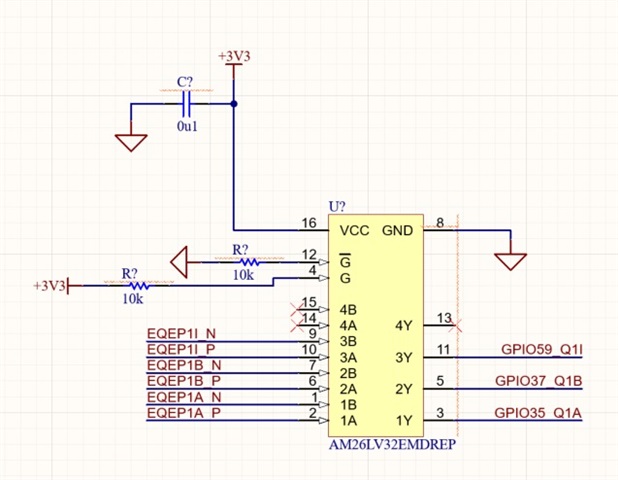
I currently have 3 differential pairs that  need to be made single-ended (0-3.3V) before entering my microcontroller.  Each differential pair is +/- 3.3V, respectively.  Is there a sample circuit or application note for the AM26LV32E that illustrates this conversion from differential pair to single-ended?

  • Differential receivers work like comparators; they compare the voltages at the two inputs. Just connect the two signals to the two inputs.

    In general, you use a termination resistor (once, at the end of the bus) that matches the cable's characteristic impedance to avoid reflections at high-speed signal edges. For very low speeds and when you do not care about EMI, you can omit the resistor.

  • Thanks, Clemens. I'm mostly concerned with G and G_BAR. Can these be pulled High and Low, respectively? Additionally, can unused pins float? See schematic below:

  • Hi Nicholas,

    G can be pulled to VCC and /G can be pulled to GND as shown without issue - it will keep the device always active. You can technically leave either G or /G floating - as both are connected to an internal OR gate - so only 1 input needs to be defined - but using both as shown is no issue. 

    For unused inputs you can leave them floating on this device. The A/B pins are open fail-safe because they are weakly biased (A to VCC and B to GND) so leaving them floating would create a "high" output on the corresponding Y pin. So yes you can leave them  floating. 

    Please let me know if you have any other questions!

    Best,

    Parker Dodson

  • Thanks, Parker.