This thread has been locked.

If you have a related question, please click the "Ask a related question" button in the top right corner. The newly created question will be automatically linked to this question.

DS90UB953-Q1EVM: Compatibility between DS90UB953 EVM and DS90UB954 EVM while using DVP mode for FPD-Link III on both devices

Part Number: DS90UB953-Q1EVM
Other Parts Discussed in Thread: ALP, DS90UB953-Q1

In our previous generation of the product we design we have used a DS90UB933 serializer for providing the video output data to in-vehicle displays. Since this serializer received parallel data input (using RAW10), the deserializer chips (DS90UB934, DS90UB936) were configured for the FPD-Link III interface using DVP input (RAW10).

We are currently evaluating the possibility to change DS90UB933 to DS90UB953 - this serializer will use MIPI CSI-2 as input but needs to work with DVP mode configured on the FPD-Link III interface. Using two EVKs, DS90UB953 EVM and DS90UB954 EVM, we are trying to configure them to work in DVP mode on the FPD-Link III interface.

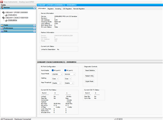
If we change the Input mode for the DS90UB954 deserializer to RAW10 and change the DS90UB953 serializer register 0x03 MODE_SEL to 0x5D (FPD_COAX set, MODE_OV set, MODE set to 101 - DVP External Clock Mode) we are able to see Link status set on the DS90UB954 deserializer while the Link status is unset on the DS90UB953 serializer.

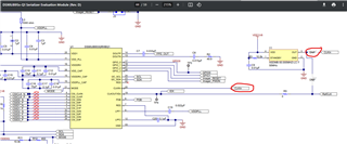
As a prerequisite for the previously described steps, we have connected the output of Y1 (external clock) to the CLKIn trace that leads to the DS90UB953 serializer CLKIN pin.

We are unsure if we need to change other register settings on the serializer or deserializer in order to have a working link between the deserializer and serializer. We require TI support on this topic so please let us know what to change/verify on the serializer or deserializer (registers, EVM updates, etc.).

  • Hello,

    Thank you for your question. If the input data is MIPI CSI-2, why does the DS90UB953 and DS90UB954 need to operate in DVP mode? Is a parallel data output needed for the system? Normally, DVP mode is used with MIPI CSI-2 data for compatibility with an older generation deserializer, but the DS90UB954 is a CSI-2 deserializer so this would not be necessary. Are you changing the DS90UB954 mode using the registers or is it set to DVP mode using the mode pin at power up?

    Regards,
    Darrah

  • So, what we currently have the following video output interface configuration is:

    DS90UB933 (DVP, RAW10) - DS90UB934 (DVP, RAW10)
    DS90UB933 (DVP, RAW0) - DS90UB936 (CSI-2, RAW10 configured for DVP input) ; since there is on DS90UB936 EVM, we are using DS90UB954 EVM instead for now, we plan to replace the chip from the EVM with DS90UB936 if we manage to have a working FPD-Link interface between 933 and 954.

    We intend to replace DS90UB933 with DS90UB953 without requiring any changes on the deserializer end. The deserializer is part of an in-vehicle display that we do not produce and cannot modify from the serializer end. The question is if it is possible to use DS90UB953 (in DVP mode) with DS90UB934 and DS90UB936 that are configured today to work with DS90UB933.

    To answer your last question, we are changing DS90UB954 mode using the mode pin set to RAW10 (we have tried also changing it during runtime via register settings if the mode pin was set to CSI2 at startup). As far as we could see, the deserializer seems to lock the link - the serializer is upset if the configuration is DVP on both sides.

    Thanks,
    Lucian

  • Hi Lucian,

    Thanks for these details. Yes, it is possible to program the DS90UB953 in DVP mode to be compatible with a DS90UB934 or DS90UB936. This app note has more details and may be a good resource as you continue system design. When the DS90UB953 is configured for DVP mode, some of the device functions are either not available or limited in order to remain compatible with the DVP devices. The lock or link status (indicated by register 0x52) is one of these features, and will not function when in DVP mode. This is likely why you are not seeing a link status in ALP, even though the physical connection is stable. To verify this, the deserializer lock register can be used. If register 0x4D of the DS90UB954 shows that the deserializer has a stable lock, then the link between the devices is good and stable. For additional verification, error registers can also be checked routinely to verify that there are no errors occurring across the link between the serializer and deserializer.

  • Hello Darrah, 

    Thank you for the confirmation regarding the compatibility between DS90UB953 with DS90UB934 and DS90UB936 in DVP mode. Thank you for sharing the application note, it helps very much in regards to the configuration of the serializer chip.

    We would like to understand how to achieve the following requirement from the Application Note related to clock synchronization (external to the serializer to the CSI clock), since we are providing the video output stream and we are not using an image sensor to do that.


    NOTE: CSI-2 input data provided to the DS90UB953-Q1 must be synchronized to the Input frequency applied to CLKIN when using DVP external clock mode.
    ...
    It is important that the sensor be synced to the external clock (either directly or by the DS90UB953-Q1 CLKOUT), because a variation or drift in CSI-2 data could cause buffer overflows.  
    ...

    Have a nice day,
    Lucian

  • Hi Lucian,

    I'm glad the application note was helpful. What this synchronization requirement means is the input data must be operating on a synchronized clock or frequency with the signal seen on the CLKIN pin of the device. The second excerpt refers specifically to a sensor, which is why it states, "either directly or by the DS90UB953-Q1 CLKOUT". Since a sensor will normally require an input clock to generate the data with, the options to synchronize that clock would be to either use the same clock signal for the sensor and the DS90UB953 (directly) or generate the input clock from the DS90UB953 (CLKOUT). 

    If you are not able to generate or modify the video output stream to have a synchronized clock (assuming it is not already synchronized), another option would be using a clock generator IC to generate a synchronized clock from the CSI clock. There are some example clock options in Table 15 of the application note.