Other Parts Discussed in Thread: TFP401A, TFP401
Hello TI team,
Can you please clarify output timing parameters of TFP401A device.
We saw that output setup and hold time values are given in table 7.7 and Figure 8-4 datasheet. We want to interface the output signals of TFP401 device with our LVDS serializer chip timings.
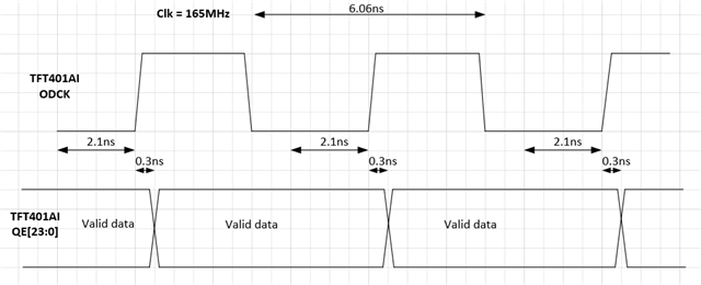
If you look at the Figure 8-4 in the datasheet, output clock "ODCK" changes with reference to data output (RGB). Our question is, how do you interpret the datasheet timing values for the output timing parameters?
Could you please clarify when does the output data (RGB) change with reference to clock output signal? If we set "OCK_INV" = High, Do I need to set rising edge sampling or falling edge sampling in my serializer chip to meet timing parameters?
thank you,
Johnson John