This thread has been locked.

If you have a related question, please click the "Ask a related question" button in the top right corner. The newly created question will be automatically linked to this question.

TMDS171: Problems with clocks

Part Number: TMDS171
Other Parts Discussed in Thread: TMDS181

Hello, I have a question about using TMDS171.

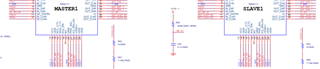
I am using two TMDS171 devices in a single channel, with each device handling three of the six TMDS inputs, to accommodate a total of six TMDS inputs.

I'm using the clock signal of the TMDS inputs from the master TMDS171 as inputs, feeding the master output into the slave input, and using the slave output as the final output.

It appears that when using TMDS dual, the clock signal output from the master differs from the input clock signal.

Is there a solution to using pinstrap mode?

  • Hey Donghyun,

    What are the differences between the master and input clocks? Is it a frequency or swing issue.

  • Hello, Donghyun,

    You should not be using the output CLK of the TMDS181 to feed through to the input of another TMDS181 whose data lanes are not associated with that CLK.

    Thanks,

    Zach

  • "The master and slave divide the 6 incoming data on a single connector. Although the data is divided into sets of 3, the clock comes in through the connector as a single entity, as illustrated in the diagram. Would this configuration pose any issues?"

  • Hello,

    You should not feed through the clock from the TMDS171 device to another.

    Thanks,

    Zach

  • "I have another question. Can the TMDS171 operate in retimer mode even if the pixel clock is below 100MHz?"

  • Hey Donghyun,

    If the pixel clock is below 100MHz the device will automatically swap to redriver mode. However, using the DEV_FUNC_MODE register you can use retimer mode for data rates below 1GHz, i.e. pixel clocks less than 100MHz.

    From datasheet 

    "At pixel clock below about 100 MHz, the TMDS171 automatically bypasses the internal retimer, and operates as a redriver. When the video source changes resolution, the internal retimer starts the acquisition process to determine the input clock frequency and acquire lock to the new data bit streams. During the clock frequency detection period and the retimer acquisition period that last approximately 7 ms, the TMDS drivers can be kept active (default) or programmed to be disabled to avoid sending invalid clock or data to the downstream receiver. The TMDS171 can support retimer mode across the full data rate range of 250 Mbps - 3.4 Gbps by setting DEV_FUNC_MODE bits at reg0Ah[1:0], See Table 9. For compliance testing such as JTOL for 480 Mbps the PLL must be forced to lock."