This thread has been locked.

If you have a related question, please click the "Ask a related question" button in the top right corner. The newly created question will be automatically linked to this question.

DS90LV019: Unexpected D+/- output

Part Number: DS90LV019

Hello,

My customer has unexpected outputs from D+/- as shown below.  They expect LVDS signals, but these aren't.

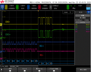
Their current schematic is shown below.  There 2 PCBs where PCB1 has FPGA and PCB2 does DS90LV019.  These PCBs are connected by connectors.  The datasheet on page 3 says VOD=360mV and VOS=1.25V, but the waveform shown above doesn't show such values, but full swing between 0V and 2.5V.

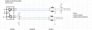
Would you please tell me how they can fix this issue?  I think they should remove the pull-up/down resistors of 4.99kOhm, but they say these resistors are for fail-safe and these would be required for the receiver which is FPGA in this case.  That's why they put pull-up/down resistors.  The datasheet figure 10 shows fail-safe circuit on input terminals(RI+/-), but it doesn't do for output pins, DO+/-. 

Best Regards,

Yoshikazu Kawasaki

  • The fail-safe resistors are OK.

    LVDS outputs are aiming for 3.5 mA, so the voltage depends on the resistance. This looks as if the termination resistor on the other side is not connected.

  • Hello Clemens-san,

    Thank y0u very much for your comments.  They say in some conditions, the FPGA can't receive correct data, but even it the FPGA gets correct data, the DO+/- are almost the same.  It means the connection between DS90LV019 and FPGA should be OK.  Therefore they're worried if the schematic may be wrong.

    Best Regards,

    Yoshikazu Kawasaki

  • The schematic looks OK.

    This sounds as if there a problem with the connection. Measure the signals at both sides.

  • Hi Yoshikazu,

    Can you verify they have that 100 ohm resistor populated? From the looks of it the D- signal looks like it's at GND, normally we would expect a bit of an offset when you have fail safe biasing when the lines are idle. This makes me think Clemens's analysis is correct, the scopeshot collected looks like it's not connect to the receiver or the 100 ohm resistor may be absent.

    -Bobby

  • Hello Clemens-san, Bobby-san,

    Thank you very much for your support.  As Bobby-san mentioned, the termination resistor of 100Ohm wasn't populated correctly.  They fixed the resistor and confirmed it worked well on their system.

    Best Regards,

    Yoshikazu Kawasaki