This thread has been locked.

If you have a related question, please click the "Ask a related question" button in the top right corner. The newly created question will be automatically linked to this question.

AM26C31: ESD & EOS Protection for RS4xx Drivers & Receivers

Part Number: AM26C31
Other Parts Discussed in Thread: ESDS314, AM26LV31, AM26C32, AM26LV31E, TXU0104, TXU0102, TXU0101, TXU0304, CD4010B, TXH0137D-Q1

Hello Community,

We are selecting ESD & EOS protection for our RS4xx use case. We anticipate a fairly noise-free environment in our use case, however designing for maximum robustness, we have selected AM26C31/32 pair. I want to understand the TVS Diode selection criteria best suited for these devices. We understand the Ideal Breakdown Voltage: Assuming +-7V on the A & B pins, a minimum of 7V is a good choice. But we already have ESDS314 in our inventory & want to evaluate if we can use the same for AM26C31/32. Kindly suggest for following pointers.

  1. Can we use Uni-directional TVS as we know A & B pins by default?
  2. How is the output voltage on A/B side related to the input voltage? Assuming 5V VCC, what do we expect the output on A/B to be, is there any direct relationship here?

Kindly guide at earliest.

  • The output voltage will be between 0 V and 5 V, typically between 0.2 V and 3.4 V.

    Do you really need 5 V logic signals? For a 3.3 V system, consider the AM26LV31(E)/32(E) instead.

  • Hello Clemens,

    We already have placed the order for AM26C32IDR/32IDR as they are the lowest cost versions.

    & yes, we want 3.3V logic signals, so can we directly interface these with 3.3V UART signals?

    (In the datasheet VIH & VOL levels are 2V & 0.8V we considered those)

    Also, do can we use the same C31/C32 pair for RS-485 full-duplex communication? The C32 Datasheet mentions it can accept RS-485.

    Frankly, I am not sure if at PHY level RS422 & RS485 might differ as much as to warrant a use of different pair of drivers & receivers, can you guide us on this?

  • Hi Neet,

    First - AM26C31 is not rated to +/-7V on its differential bus - its -0.5V to 7V - RS-422 only requires the receiver to be rated to +/-7V inputs as RS-422 is multi-drop which means there is only 1 driver on the bus. The large common mode input range exists because there could be a ground potential difference at the receiver compared to driver. It is assumed there will be no ground potential shift at driver - since it is sending signals in reference to its own ground. So only the AM26C32 has the +/-7V rating (its the receiver) 

    Next the diode that you have chosen - is risky. Its a 3.3V diode and this part is most likely going to be outputting >3.3V on its bus pins. Generally I'd suggest a 5V diode. 

    For your direct questions:

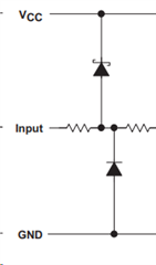
    1. Unidirectional diodes are only going to protect the bus in one direction (either positive of negative voltages) - not both unless you have 2 unidirectional diodes - one from GND to line and one from line to VCC  - something like this:

    But in general - I wouldn't ever recommend single ended diodes on differential bus. I don't have  a TI diode to recommend - I wouldn't recommend our diodes for RS-4xx applications as we generally do not have a great offering for RS-4xx diodes . I would get a 5V bi-directional diode on the receiver A/B pins and diodes to keep driver pins between 0V and 5V typically. 

    AM26C31 has Y and Z pins for differential bus - they are the outputs - the AM26C32 has A and B pins for differential bus and they are inputs. 

    The input voltage into AM26C31 has no direct relationship with output voltage beyond if input voltage is >2V the AM26C31 will output a high on Y and a low on Z and if the input is < 0.8V than the device will output a high on Z and a low on Y. It is dependent on loading what the actual analog voltage is - but theoretically it could be up to VCC - VD (probably won't be that high - but that is what I'd assume is the high point when designing a system).

    Another note - this is a 5V device; while you can control the device from a 3.3V controller - that controller either needs 5V tolerant inputs or there needs to be a level shifter from output of AM26C32 to controller as it can output up to VCC potentially. The AM26LV31E/32E could operate at 3.3V without the need for a level translator. It is more expensive - but I am not sure if the price savings are going to account for the increase circuits that you will need on your board. 

    In terms of robustness - the best quad devices we have are the AM26LV31E/32E - since its seems you are operating largely a 3.3V system this is honestly what I'd suggest. In general RS-422 is just substandard RS-485 - it does the same things RS-485 does but worse. The catch is that our best quad devices are RS-422 and the performance negatives compared to RS-485 don't seem to be important to the designers who utilize the quad devices in the AM26 families. If you truly want the best system performance at a very low level - you'd switch to RS-485 and use our modern devices - but the IC count would quadruple so its not very practical - so that is why I'd suggest the AM26LV31E/32E families.

    If you continue with the AM26C31/32 pair a few notes:

    1. Any single ended output from the AM26C32 could be up to 5V  - the controller has to be able to handle that or you need a level translator. If this isn't planned in the design currently - the design will have a high chance of failure with 3.3V controller. 

    2. Protection diodes on the bus - driver outputs must remain in the range of -0.5V to 7V and the receiver +/-7V. So using a 3.3V diode is not the best idea - a bi-directional diode (5V would probably be best) would most likely prove the most helpful on the receiver end of bus. If you are trying to protect driver end of bus - it will need to be protected between -0.5V to 7V. 

    Please let me know if you have any other questions. 

    Best,

    Parker Dodson

  • Hello Parker,

    Thank you very much for this detailed response, this helps us understand the key aspects now. & yes, the input pins at the MCU are all 5V tolerant.

    Also, just in case which level translator would you recommend for this use case with smallest footrprint? If you could direct me to any family it would be helpful for us.

  • Hi Neet,

    I am going to loop in our level translator team as they are probably going to be the best resource for selecting a level translator.

    Best,

    Parker Dodson

  • TXU0101/TXU0102/TXU0104, depending on how many channels you actually need.

  • Perfect, we have some of TXU0304 in our inventory, we will experiment with these. I would appreciate to get a schematic of AM26 x TXU0xxxx x TVS evaluated in the next 3 days once we prepare it, is there a mail where i can share it for reference evaluation? Do suggest as we have to adopt these devices in almost all the off-board communication and your feedback shall help build confidence in the design.

  • Hi Neet,

    You may share schematic here for review or share the TXU / level shifter schematic using txp_systemapps@list.ti.com for further review, thanks.

    Best Regards,

    Michael.

  • Hello Michael & Clemens,

    To clarify a use case where we are using a pair of AM26C31 & C32 for 4 UART transmission. We plan to check if using a single STP cable for both in half-duplex mode by subsequently enabling/disabling either of the C31 or C32 is a good idea by design? Assuming the firmware shall take care of the sequencing, would you recommend implementing this approach to reduce the number of vables required for data transmission in half duplex using the G or G' pins on the driver & the receiver?

    Kindly guide.

  • Yes; disabling the drivers allows you to implement a half-duplex bus.

  • Hello Clemens,

    We found CD4000 family interesting - especialy the CD4010B as it might help our other use cases where we plan to translate 10V signals down to 3.3V logic input for the MCU within 1Mbps maximum. Can you confirm is this is suitable for optional level shifting of C32 5V output to 3.3V?

    Also, the MCU pins are 5V tolerant - this should ideally negate the need for a level translator, right? Any other practical limitation we may face when using the C32 decives without an intermediate level translator assuming the MCU pins are 5V Tolerant & accepts & works with 5V logic signals?

    Do you have any recommendation for series current limiting resistor that can further safeguard this configuration with no level shifting?

    Kindly guide.

  • Hi Neet, 

    I would recommend the level shifter if such higher voltage of 10V is present even if MCU is 5V tolerant. Note that you may also use resistors or a divider network for the intended design. However, they may come with tradeoffs such higher power consumption with little to no built in ESD protection.

    Furthermore, you may also use the CD4000 family or the new TXH family (TXH0137D-Q1), thanks.

    Best Regards,

    Michael.

  • CD4000 devices are optimized for higher voltages, and are quite slow at 5 V or lower. And they have no guaranteed characteristics at 3.3 V. But 1 Mbps is likely to work.

    5-V tolerant pins can accept 5 V signals.

    A current-limiting resistor works only for inputs that have clamping diodes to VCC. 5-V tolerant inputs do not have them.