This thread has been locked.

If you have a related question, please click the "Ask a related question" button in the top right corner. The newly created question will be automatically linked to this question.

TXB0104-Q1: TXB0104QPWRQ1 : Need support

Part Number: TXB0104-Q1
Other Parts Discussed in Thread: SN75173, , SN74AHC125-Q1, TXU0204-Q1, TXU0304-Q1

Hello,

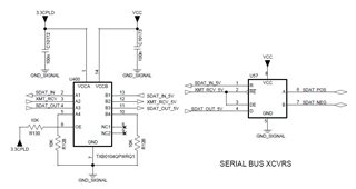
I have recently incorporated the TXB0104QPWRQ1 component into our design. Here is the circuit diagram. It essentially converts 5V to 3.3V.

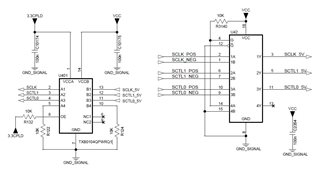
VCC = 5V, 3.3CPLD = 3.3V

But it is not converting to 3.3V. The IC U42 in the picture is SN75173D, and the output (3.3V) of the level shifter goes to CPLD pins.

Could you please verify the circuit diagram? Do you see any issues with it?

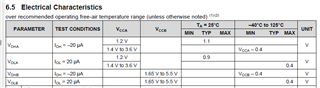
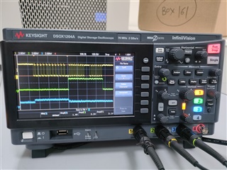
Also, what if the SCLK_5V, SCTL1_5V, SCTL0_5V are at lower voltage i.e. 3.2V shown in picture below. As we are getting output of 1.2V Refer amplitude 2 (input to level shifter) and 3 (output from level shifter)

Do let me know. 

Thanks, 

Amol Bagul

  • The SN75173 has TTL outputs (see figure 7-1), so it violates the VIH specfication of the TXB0104-Q1. (But in this case, the inputs appear to work anyway.)

    The TXB0104-Q1's output have a drive strength of only 20 µA. Your schematic does not show the load, but it obviously is larger.

    Unidirectional signals do not require a bidirectional translator. For translating TTL signals to 3.3 V, you should use a buffer or translator with overvoltage-tolerant 3.3 V inputs, e.g., SN74AHC125-Q1.

  • Hello,

    Load in this case is CPLD - 5M240ZT100C5N (Intel), and I think the strength is 20mA. Is it right not to use a unidirectional translator? Does that mean these bidirectional ones will not work in this case?

    Also, if the voltage on the line (TTL output of SN75173) is less than 4V or around 3.2V, do we really need translators?

    The same part (TXB0104-Q1) has been used in the following cases. Kindly review and suggest if these are the right choices or if there are alternatives.

    1.  Here, signals are bidirectional and load is CPLD - 5M240ZT100C5N (Intel), SDAT_IN, XMT_RCV, SDAT_OUT are connected to IO pins of CPLD. 

    2.  U166- ADC - LT1863CGN, VCCA is connected to CPLD - 5M240ZT100C5N (Intel)


    Thanks, 

    Amol Bagul

  • Also, Do we have Simulation model available? I see, only IBIS model is there.

  • The TXB's drive strength indeed is 20 µA.

    The internal pull-up resistors of the 5M240ZT100C5N are too strong for the TXB. (I do not know if the pull-ups are enabled in your case.)

    In order to allow bidirectional transmission, the TXB has deliberately weak output so that other devices can override the voltage. Your schematics do not show the connection to the CPLD, or if there are any external pull-up/-down resistors. In any case, your measurements shows that the TXB cannot drive the CPLD's inputs. A unidirectional translator would not have these problems.

    The TTL output voltage depends on the load. I do not know if it would be too high for the CPLD.

    1. These signals are not bidirectional; you have three unidirectional signals. The TXU0204-Q1 or TXU0304-Q1 could handle this.

    2. The TXU0304-Q1 could handle this.

  • Thank you for your suggestions.

    Where did the 20 uA value come from? The datasheet only shows the IOH value, which appears to be a test condition, correct?

    Here are the CPLD connections for 3 drivers mentioned in above -

    Can TXU0204-Q1 or TXU0304-Q1 be used for all three locations, considering that all three drivers are unidirectional? Please provide your recommendation.

    Additionally, is there a simulation model available, such as LTspice, for these parts? I noticed only IBIS models on the website.

    Lastly, does TI offer 3-5 samples on a quick basis for validation in our design?

    Thanks, 

    Amol Bagul

  • Yes, 20 µA is a test condition. This is the only output current for which an output voltage is guaranteed.

    All your signals are unidirectional (that is, each individual signal does not change direction), so TXU translators can handle them.

  • Hi Amol,

    In addition, please note that the models we provide are the IBIS models available.

    Also, yes you may order free samples (samples.ti.com) thanks.

    Best Regards,

    Michael.

  • Hi Clemen,

    Few clarifications needed. In datasheet of TXB0104-Q1 / TXB0108PWR, "IO Continuous output current ±50 mA" and IOh mentioned as 20 uA.

    So, regarding Drive strength of TXB0104-Q1 / TXB0108PWR, can we read minimum drive current Ioh = 20uA and 

    maximum Drive current which is Continuous output current IO = 50mA.

    Request you to let me know if my understanding of IO and Ioh is not correct?

  • The 50 mA is an absolute maximum rating, i.e., it says you must not try to draw more than 50 mA from an output. Due to the high impedance of the outputs, this is not possible anyway.

    The 20 µA limit is the maximum current that the datasheet guarantees.

  • Hi Clemens,

    In my design signal is not continuous and it's pulsating so average current requirement will be less so for example if i draw average current of approx. 8mA to 10 mA and you have mentioned 50 mA is an absolute maximum continuous current rating, Can you please suggest it that is fine ?

    Secondly regarding 20uA rating, i read it as Minimum current guaranteed to detect the logic at Minimum VCCA-0.4 as per datasheet (refer screenshot below, Electrical Characteristics, page 5 of datasheet). Please let me know your thought.

    Also, as side note, if you think that TI needs to do Improvement in its datasheet by adding more clarity so that it will help Designers with better and clear understanding.

  • Hi Puspam,

    8 to 10 mA will not damage the device. However, since the device is tested and recommended for 20uA for it's auto bidirectional feature, 8 to 10 mA operation is not guaranteed. The TXU recommendation guarantees the application's operation.

    You are correct. I.e higher than 20 uA do not guarantee the VOL / VOH levels.

    Note that if these levels are around 1/2Vcc, high shoot through current may occur possibly above the abs max values for damages.

    See Understanding and Interpreting Standard Logic datasheets - section 4.5.7 and [FAQ] How does a slow or floating input affect a CMOS device? - (2) oscillation further clarifying, thanks.

    Best Regards,

    Michael.