This thread has been locked.

If you have a related question, please click the "Ask a related question" button in the top right corner. The newly created question will be automatically linked to this question.

THVD1424: Difference between RS-422 and RS-485 4-wire implementation

Part Number: THVD1424
Other Parts Discussed in Thread: AM26LV32, AM26LV31

Hello,

I am trying to understand the difference between RS485 and RS422.  I have read as many TI app notes as I could find along with a few from other sources.  I have a strong understanding of the electrical minimums and maximums.  As I understand them, both only specify hardware characteristics and nothing in software (different than CAN which is hardware and software).

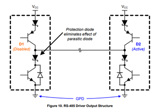
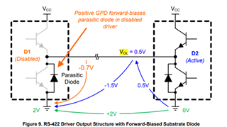
I would like some clarification on the transceivers used for each, I understand that most RS-485 transceivers are compatible with RS-422, but not the other way around.  RS-485’s driver must have a tri-state transceiver so that when more than one transmitter is on a bus the active one goes high/low and the inactive ones are High-Z.  Is this the same case for conventional RS-422 transceivers?  I would like to reference a Renesas app note that shows the two conventional transceiver types:

AN1989: RS-422 vs RS-485: Similarities and Key Differences (renesas.com)

For the THVD1424 does it align with the RS-485 transceiver with the shottkey diode in series?  Possibly swapping out the BJTs with MOSFETs.


My confusion arises when comparing RS-422 and RS-485 4-wire schematics.  RS-422 is meant to be multidrop(1 MASTER transmitter and multiple SLAVE receivers), while RS-485 is meant to be multipoint(multiple transmitters and multiple receivers).  For RS-422 if a SLAVE wanted to transmit back to the MASTER, would RS-422 mandate that only 1 SLAVE transmitter be connected to the MASTER’s receiver to comply with only 1 transmitter allowed on a pair of wires?  Below is a depiction of what I am trying to ask.

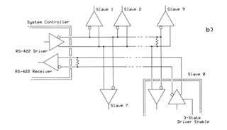
Above is my understanding of RS-422, although the 3 state/tri-state driver is not needed since it is the only transmitter on that pair of wires and aligns with the RS 485 transceiver in the Renesas app note.

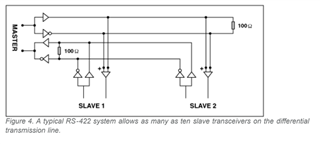
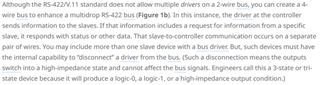
Maxim depiction taken from Guide to Selecting and Using RS-232, RS-422, and RS-485 Serial Data Standards | Analog Devices.  Here 2 SLAVE transmitters are on the same bus, is this also RS-422?

It is reiterated here as well:

From: Basics of RS-422 and RS-485 Communications - Sealevel

Any help clarifying this would be much appreciated.  The only way I can reason through this is that a legacy RS-422 design got a new RS-485 transceiver put in it and enabled the multiple transceiver SLAVE to MASTER communication route and kept the RS-422 branding since there is technically a master.


Thanks for the help


  • RS-422 specifies how to transmit unidirectional signals. If you want both directions, you need two differential signal lines.
    RS-485 specifies how to transmit bidirectional signals over a half-duplex, shared bus.

    RS-485 can have multiple drivers and receivers. RS-422 has exactly one driver; it can have multiple receivers, but in practice, it is unlikely that having more than one would be useful. RS-485 drivers must be able to be deactivated; RS-422 drivers sometimes support this, but only to save power. (The circuit above with multiple slave drivers is labelled "RS-422" because you have four wires, but this is wrong; having multiple drivers on the bus actually is RS-485. But neither is it identical with a 'normal' RS-485 bus where everything goes over the same bus.)

    RS-485 needs termination resistors at both ends of the bus. RS-422 needs termination only at the end of the bus opposite from the driver.

    There are some electrical differences, but RS-485 transceivers are compatible with RS-422.

    RS-485 transceivers always include both a driver and a receiver. For RS-422, there a devices with only drivers or only receivers (e.g., AM26LV31/AM26LV32).

    Half-duplex RS-485 transceivers can be used for RS-422 if you disable the driver or the receiver. Full-duplex RS-485 transceivers can be used for two RS-422 connections, in both directions; they can be used for a half-duplex RS-485 bus if you connect the driver and the receiver pins together.

    See the RS-422 and RS-485 Standards Overview and System Configurations Application Report.

  • Thanks for getting back to me.  This is starting to make a lot more sense, I had a feeling the circuit above had a miss labeling and wanted to make sure I knew where the line was between RS-485 and RS-422.  

    From all the information I have gathered if the electrical characteristics could either be RS-485 or RS-422, since there is over lap, it sounds like the deciding factor is how many drivers are on a differential signal line. Only 1 = RS-422, More than 1 = RS-485.

    Correct me if I am wrong but this distinction between the two is made purely on what is happening on one differential line, assuming they are electrically compatible with both RS-422 and RS-485.  In theory for the mislabeled one above could the Master transmit bus be RS-422 and the Master receive bus be RS-485 or if one of the differential lines is RS-485 then regardless if the other differential line is unidirectional it is still RS-485 configured?

    I do see your point above though how this would be very unusual, but am trying to complete my understanding with this hypothetical.

    I also wanted to follow up on the RS-485 resistors showing up on both the driver and receiver ends of the transmission line for a 4-wire implementation. Theoretically you want the receiver to have a matched impedance to its transmission line warranting the 100 Ohm resistor to reduce reflections, very similar to LVDS. Is there a reason to add a resistor next to the driver if RS-485 is operating in full-duplex?

  • Yes, the master transmit bus is RS-422, and the master receive bus is RS-485. (But in practice, it does not really matter how you label it; you just have to find transceiver chips that have the correct number of drivers and receivers,  and be half or full duplex.)

    A bus/cable has two ends. You need termination resistors at those ends where it is possible that there is not an active driver (an active driver is stronger than the resistor). So on an RS-422 bus, with the driver at one end, only the other end needs termination. On an RS-485 bus, you typically have at least two drivers, each of which is inactive some of the time, so both ends need termination.