This thread has been locked.

If you have a related question, please click the "Ask a related question" button in the top right corner. The newly created question will be automatically linked to this question.

DP83867IRPAP-EVM: DP83867IRPAP-EVM Register Access through USB-2-MDIO

Part Number: DP83867IRPAP-EVM
Other Parts Discussed in Thread: USB-2-MDIO, UNIFLASH, DP83TG720EVM-MC, MSP430F5529, DP83TC812EVM-MC, , DP83867IR

Hello

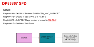
     The Object is to detect the SFD of the ethernet frame using DP83867IRPAP-EVM which I bought recently from Texas Instruments.

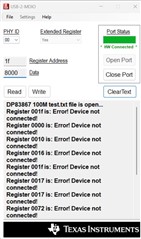
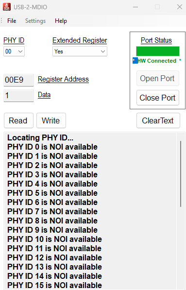
     This question is about read/write registers of DP83867IRPAP-EVM through USB-2-MDIO.

I have read the documents of USB-2-MDIO Software Tool (ti.com)  and  How to Configure DP83867 Start of Frame Detect (ti.com)

The questions are : 

1. As per How to Configure DP83867 Start of Frame Detect (ti.com), We have to program registers in order to detect SFD of the ethernet frame.

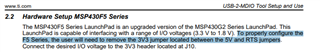
   Do I need any SW Driver between USB-2-MDIO SW and the board DP83867IRPAP-EVM. If so, Pls let me know which one is needed ? 

 2.   USB-2-MDIO software is installed in the computer and DP83867IRPAP-EVM is connected with the computer through ethernet.

 Is there anything else needed in order to program registers on the board DP83867IRPAP-EVM ?   

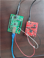
3. The DP83867 EVM supports serial management (MDIO/MDC) and RGMII/GMII/MII MAC interfaces. Serial management interface is accessible though J8.

The board DP83867IRPAP-EVM  got MDIO and MDC pins.   The MDIO is located at pin 37 and MDC is located at pin 39.

I need to know how can I connect  Serial Management Interface J8 with the Computer where USB-2-MDIO SW is installed ? 

If any Special interface (J8 interface) needed, please let me know where can I get it.


Look forward hear the detailed answer. 


Thanks

Krish

  • Hi Krish,

    The EVM does not have a MCU which USB2MDIO relies upon, specifically MSP430F5529LP. To ungate, I would recommend obtaining this launchpad to assist in evaluating this device. You would then need to flash the launchpad using Uniflash, a TI software, using the attached file, and the connect launchpad pin 4.1 to EVM's MDC pin, and 4.2 to MDIO pin, along with connecting GNDs between boards. Then, you will be able to evaluate the registers of the device. Apologies for the unclarity.

    Sincerely,

    Gerome

    7357.msp430-usb-to-mdio-universal-v3.04.txt

  • Hi Gerome

    Thank you for the answer.

    You specifically mentioned  MSP430F5529LP.  May I know the reason why specifically  MSP430F5529LP ? and why not  MSP-EXP430G2ET ? 

    Would you point me a TI Document that describe the overall connections between MSP430* launchpad and EVM board ?

    Do I need any drivers to be installed for this EVM board ? 

    Thanks

    Krish

  • Hi Krish,

    Most of our newer EVMs (like DP83TC812EVM-MC and DP83TG720EVM-MC) have MSP430F5529 on them (as an IC on the board instead of connections to an external board) and thus is a good starting point. There is no drivers needed to be installed for this EVM as it is a standalone PHY.

    Sincerely,

    Gerome

  • Hi Gerome

    You mentioned about newer EVMs have builtin IC MSP430F5529.

    But, In my case, i have DP83867IRPAP-EVM and not sure it is a newer EVM or not.

    So, i still have to connect MSP430F5529 with my board DP83867IRPAP-EVM externally ?

    Pls confirm MSP430F5529 launch PAD is compatible with with board DP83867IRPAP-EVM.and connection need to be done externally.

    Pls confirm the above before i purchase them.

    Thank You.

    Krish

  • Hello Krish,

    You are correct. You will need to connect MSP430F5529 externally to DP83867IRPAP-EVM. To do this, you will need to flash the launchpad with uniflash using the previously attached flash file, connect pins 4.1 (MDC) and 4.2 (MDIO) to the respective parts in the EVM, power on the EVM and launchpad, use USB2MDIO.

    Sincerely,

    Gerome

  • Hello Gerome

    1.  Connected pins 4.1 (MDC) and 4.2 (MDIO) to the respective parts in the EVM

    2. I did flash the Launch PAD with the text file that you sent in the 1st post in here. => Successfully done.

    3. Tried writing/Reading the Registers using USB-2-MDIO

    4. But, I am getting the "Device not Connected" Message when I read or write register. 

    5. How do we fix the "Device not connected" Issue ? 

  • Hi Krish,

    Please ensure that the PHY is on and connected to the launchpad before powering on the launchpad via USB.

    In addition, I noticed that the VDDIO of the EVM is at 2.5V. With the launchpad being 3.3V, there is a conflict of VDDIO domains. To bridge this gap, can you please disconnect the 3.3V header in the middle of the launchpad, and then attach a power supply to the 3.3V pin at the bottom of the launchpad with this supply set to 2.5V. This will make the launchpad 2.5V VDDIO compatible.

    Sincerely,

    Gerome

  • Hi Gerome

        Yes, I did power up EVM - PHY First before the Launch PAD.  But, still getting "Device not connected".

    Are there any jumpers need to be removed in the Launch PAD (MSP430F5529) as per the following TI guide ?

  • Hello,

    Edited my response above for 2.5V operation.

    Sincerely,

    Gerome

  • Hi Gerome

        Need explanation on your last answer.

    >>In addition, I noticed that the VDDIO of the EVM is at 2.5V. With the launchpad being 3.3V, there is a conflict of VDDIO domains. To bridge this gap, can >>you please disconnect the 3.3V header in the middle of the launchpad, and then attach a power supply to the 3.3V pin at the bottom of the launchpad > >> with this supply set to 2.5V. This will make the launchpad 2.5V VDDIO compatible.

    1. Launchpad is already powered by 5v power supply at the top port through USB.  Do you want me provide another additional 3.3v power supply to the right bottom pins ?   Two different power supplies ( 5v and 3.3v) at the same time to the launchpad ?  

    2. As per the following diagram, the 3.3v power supply is derived (internal to launchpad) from 5v power supply and the 3.3v is supplied to the Target Device (MSP430F) automatically by the launchpad.  Then,  why do we have to re-supply 3.3v at the PIN level to this launchpad while 5v is already supplied through USB.

    Page 10 from MSP430F5529 LaunchPad Development Kit (MSP-EXP430F5529LP) User's Guide (Rev. D) (ti.com)

    Thanks

    Krish

  • Hi Krish,

    While it may seem unorthodox, this is the correct interpretation. In your diagram, you can see the jumper in red is the 3.3V getting supplied by the LDO on top of the launchpad. We would like to remove this jumper to cut this connection off. Instead, we would like to power 2.5V from an external supply to the 3.3V header connected to the target MCU. This can be done via the 3.3V supply pin at the bottom right side of the board. Again, as the 3.3V LDO is cut off, this voltage will only be supplied from the external power supply. This is done to manipulate the VDDIO domain of the MCU to be 2.5V instead of 3.3V, thus matching the VDDIO of the PHY.

    Sincerely,

    Gerome

  • HI Gerome

    I thought I need 3.3v power supply to be applied to 3.3v supply pin at the bottom right side of the board.

    But, as per your last answer, I need 2.5v power supply to be applied to the 3.3v supply pin ? Pls confirm that I need to buy 2.5v power supply ? 

    Can you pls suggest the correct part number of this power supply that specially fit into the PINs at the bottom of the board. 

    ------------

    Also, I want to know that Is this unorthodox method is due to the MSP430F5529 launchpad ?   

    Can you pls suggest me another launchpad where I do not have to go through this unorthodox method. 

  • Hi Krish,

    This is true, the 2.5V supply needs to be connected to the 3.3V pin to supply 2.5V VDDIO to the MCU. 

    Any typical variable lab power supply should be sufficient.

    Sincerely,

    Gerome

  • Hi Gerome

         Thank you for clarification.

    I am still wondering why this unorthodox way of connecting external power supply WHILE we already provide 5v through USB to the Launchpad.

    Pls kindly explain the following questions. 

    1. Is this external power supply of 2.5v is needed due to this specific EVM such as DP83867IRPAP where VDDIO is 2.5v ?  

    2. Does the EVM such as DP83867ERGZ - R also have VDDIO of 2.5v ?  Even if I bought DP83867ERGZ EVM , I would have needed this special 2.5 v power supply ? 

    3. Let me know what combination of EVMs (?) and Launch PAD (?) would work at the same VDDIO with out the need of this unorthodox way of connecting external power supply ? 

    4.  The 2.5v Power supply is hard to get and could not find one at amazon. Does the 3v or 3.3v external Power Supply would work at LaunchPAD ?  


    Thanks

    Krish

  • Hi Krish,

    Yes, this is due to matching the VDDIO of the DP83867IRPAP EVM.

    Sincerely

    Gerome

    ____

    Update 1/25/24: Hi Krish, I would like to correct my previous statement where VDDIO of the RGZ EVM is 3.3V. It is actually 2.5V. However, I have personally tested the launchpad as is with the EVM and the connections can work as is, but may possibly need to go through the iteration of power cycling the board and launchpad multiple times for the FW to register the PHY to allow access.

    You can also utilize a secondary option; DP83TC812EVM-MC. This is an all-in-one option which can be supplied by a single USB supply and have register access via that same cable. The only drawback is that the GPIO is a NC, so to probe you would need to directly probe on the PHY pin.

    I apologize for the confusion and frustration this entire process has caused. 

    Sincerely,

    Gerome

  • Hi Gerome

       I just saw your Corrected Version of the answer. 

    1. You said "VDDIO of the RGZ EVM is 3.3V. It is actually 2.5V".   Does it mean that I still need to apply 2.5 v externally to the LaunchPAD MSP430F5529 even for DP83867ERGZ EVM ?? 

    2. You said  " However, I have personally tested the launchpad as is with the EVM and the connections can work as is, but may possibly need to go through the iteration of power cycling the board and launchpad multiple times for the FW to register the PHY to allow access. " 

    Can you pls point me the TI Spec for the above statement of how to do the the Power Cycling. 

    3.  Is this Power Cycling Process is ONLY applicable for RGZ EVM & MSP430F5529 ?   This process is not needed for DP83867IRPAP. ? 

    4. I am looking for EVM board that have the feature of => SFD IEEE 1588 timestamp.  I have only 2 options. => DP83867ERGZ  Or   DP83867IRPAP.  I have the LaunchPAD MSP430F5529.

    These EVM and Launch PAD are suggested by TI Technical Support Team. Now, I am EVM and LaunchPAD suggested by TI Technical team are not working together or not compatible and making the entire process more confusion and frustration.

    Pls suggest me what is the correct Procedure and what is the correct combination of EVM and Launchpad. 

    Please answer the above questions as well.

  • Hi Gerome, Waiting for your answer for my last post. 

    Most importantly, For the Combination of (DP83867ERGZ EVM and MSP430F5529) => Do we still need to apply external 2.5v power supply to MSP430F5529  Or, it will be work fine with just 5v power supply through USB. ? 

  • Hi Krish,

    Using 5V supply via USB should be sufficient for this, but there may need to be some iterations in power cycling to ensure the MSP is able to properly recognize the PHY. Previously, you had expressed difficulty in obtaining a 2.5V supply so I am trying to give options to work around this.

    If you are looking for an all-in-one solution to evaluate the PHY's SFD on a GPIO while also powering and accessing registers via USB, I would recommend checking out DP83TC812EVM-MC as this does have this capabilities, albeit with the GPIO pin as a NC so you would need to probe directly.

    There are also other EVMs in our DP83867IR product page which also have a MCU with our PHY for proper register access.

    I apologize for the frustration this has caused. I have noted this for next revision of these EVMs.

    Sincerely,
    Gerome

  • Hi Gerome

            Thank you for your answer.

    You suggested  DP83TC812EVM-MC as all in one solution.  But, I reviewed the Spec for this EVM.  But, it does not explicitly say that it supports start-of-frame detect IEEE 1588 timestamp.

    Can you please point me the TI Specification for DP83TC812EVM-MC where it says it supports the following.

    • SFD IEEE 1588 timestamp
  • Hello,

    You would utilize the DP83TC812EVM-MC for its DP83867 portion. As this PHY does support 1588 SFD, and has power and register access all available via USB cable, the only note is that the GPIO pin would need to be directly probed.

    Sincerely,

    Gerome

  • Hi Gerome

       As per your suggestion, I bought DP83TC812EVM-MC recently.

    I tested write/read for the PHY registers on the board and it works fine. That is great. 

    Specifically, I want to detect SFD on DP83TC812EVM-MC and should be able to check visually either through PINs/GPIO.

    The following TI Specification shown below ( Section 4, Page 3) has the procedure to detect the SFD specifically for EVMs such as DP83867IRPAP,  DP83867ERGZ-S,  DP83867ERGZ-R.   

    How to Configure DP83867 Start of Frame Detect (ti.com)

    I tried exact the same procedure on this new board DP83TC812EVM-MC  and it does Not seem to work for DP83TC812EVM-MC. 

    1. What registers ( address, data) that need to be programmed in order to detect the SFD on this DP83TC812EVM-MC.  ?   

    2. Once Step (1) is completed, What PINs or GPIO that I can check SFD detection ? 

    3. Pls let me know the complete procedure to detect SFD specific to DP83TC812EVM-MC.

    Look forward to hear from you as early as possible as my project depending on this SFD detection. 

    Thanks

    Krish

  • Hi Krish,

    This is odd as our team had recently tested this on the ERGZ EVM with no issue. The register configurations were per the app note, but the same settings should apply regardless of board.

    The procedure also requires data to be sent on the MDI so it would pass through the PHY, with the probe on GPIO_0 pin of DP83867.

    Can you please provide your procedure that you are conducting? What PHY ID? Picture of setup where the probe is connected to the pin.

    Sincerely,

    Gerome

  • HI Gerome

         The register programming that you sent was  for the ERGZ EVM.

    But, in my last post, I asked the register programming for new board DP83TC812EVM-MC ( Not  ERGZ EVM).

    Pls let me know the correct register programming procedure and Prob setup to detect SFD on DP83TC812EVM-MC.

    I have only ONE DP83TC812EVM-MC.  The packet generator can be connected to the EVM through Ethernet cable.

    Exactly which PINs on DP83TC812EVM-MC need to be probed to detect the SFD ? 

    Is the following test setup is enough to detect the SFD ? 

    Packet generator => DP83TC812EVM-MC => Probes ?  

  • Hi Krish,

    This would still work as the PHY is the same; DP83867. You will need to probe on the DP83867 pins directly per the app note.

    Sincerely,

    Gerome

  • HI Gerome

    Just for your Information :  Your previous answer is not correct and does not applicable to DP83TC812EVM-MC.  

    Correct Procedure for DP83TC812EVM-MC.  

    1. Writing 0x1080 to Register 0x04A0 

    2. Writing 0x0406 to Register 0x0452  <=  New Information.

    3. Software restart : Writing 0x4000 to Register 0x001F

  • Hi Krish,

    Which PHY are you writing to on this board?

    Sincerely,

    Gerome

  • Hi Gerome

    The SFD register for the DP83867 is different than  the one in DP83TC812. 

    Section 8.6.2.44 IO_MUX_CFG_1 Register 0x0452 is the register for configuring SFD for DP83TC812.

  • Hi Krish,

    I am curious as to why you are looking at the DP83TC812 when all of the prior debug was geared towards the DP83867. The board has both PHYs and thus you can ignore the 100Base-T1 portion of the board for all intents and purposes of your debug.

    Sincerely,

    Gerome