This thread has been locked.
If you have a related question, please click the "Ask a related question" button in the top right corner. The newly created question will be automatically linked to this question.
Hello all,
I am trying to transfer video signals 4K from DP source to an eDP 32 inches panel.
I think there are no any drivers/IC in for converting DP to eDP as they are quite much the same.
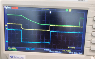
However, I have tested my board, but it seems the PC just does not recognize the panel at all.
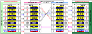
I am attaching the schematic, and will ask for some help or recommendation on how to fix the issue?
Thanks, Tsvetromir
Tsvetromir
On the sink side, you should 1M pull up to 3.3V on DAUX_P and 1M pulldown on DAUX_N.
When you connect to the PC, do you see the sink driving HPD high?
Thanks
David
Hello,
I have not tried with 1M resistors, only with 100K but even the PC does not recognize nothing to be plugged in.
Tomorrow I will measure the HPD after plugging in.
Should I connect HPD to 100K to GND or should just connect it both sides to DP and to eDP?
Thanks!
Tsvetromir
100k to GND is to prevent HPD from floating when not connected. For now, I would just connect it both sides to DP and to eDP.
Thanks
David
Hello David,
I measured HPD signal, with source cable and without the source cable, In both ways when I measure HPD, with powering the board ON, HPD goes HIGH, and stays HIGH forever. Does not matter if I plug or unplug the video cable. The HPD seems independent of the cable presence.
When I measured the HPD, AUX_P was pulled up 1M to 3.3V, AUX_N was pulled down with 1M to GND.
What was interesting with HPD is that its VOLAGE level at HIGH was about 1.96V. As far as I know it should be >2.4V to be logic 1, and below 0.8V to be logic 0. So in my case with 1.96V I am in between so I think the HPD is never being recognized as to be HIGH.
What do you think?
Thanks,
Tsvetomir
I just measured it again, and the same results I just got. I meant HPD stays always High, however I measured 2.54V now.
This panel was updated with a software for the converter board, and now this board is removed. Only my dp to eDP board is present. But i am wondering what is in the EDID EEPROM uploaded.
Hi,
Can you probe AUXP/AUXN, are you seeing any data going across AUXP/N?
Thanks
David
David,
I will check what is the status of the AUX signals.
BTW, now when using DP to DP cable, and the source is my NVIDIA Geforce, it seems that the PC DOES recognize the Panel, but it says Display 2 is not active....
I measured AUX_P with passive standard probe and can see some pulses are moving. While the PC now recognizes the eDP panel resolution but still, the panel only changes some colors: Red, Blue, Green, White continuously.
As the panel is produced in China, and they have prepared their own firmware for their converter board, I am not sure what is it now in the panel EDID memory.
Is there a way to read/write the data over the AUX channel?? I mean if there is an application for this purpose?
Thanks,
Tsvetomir
Tsvetomir
You could use the Unigraf DPA-400 to decode the AUX traffic, https://www.unigraf.fi/product/dpa-400-displayport-aux-channel-monitor/.
Thanks
David
Hi David,
Thanks for the proposal.
I still cannot get it work. I tried to shorten the cable length, proving the need of re-driver or not, but it is the same. The PC sees the monitor, recognizes the resolution needed, but still, the second monitor appears under Display settings, and I am able to extend/duplicate and so on, even the mouse arrow can be moved on the second (eDP) screen, but there is no video. Just changing colors - red/green/blue and so on.
Do you have any ideas?
Thanks
I just want to mention the structure of my schematic:
I use DP to DP cable, as a source I use the PC video card, but on the sink side, where is my converter board i have arranged the following pinout
On the sink side the Lane channels are twisted, so I have kept this pinout on my PCB. Then I have an eDP cable (shortened to 10cm) and soldered cable by cable to match the DP sink side signals. A 100K pull down on the HPD. and 1M pull up on AuxP 1M pull down on AuxN. That is all!
CONFIG1 and CONFIG2 are left unconnected at all. I even tried to pull them down with 1M but did not change anything. On the other hand, I Soldered 100nF 0402 cap on each of the Lanes, in series, but also did not helped at all.
Hi,
I use DP to DP cable, as a source I use the PC video card, but on the sink side, where is my converter board i have arranged the following pinout
Correct, for your DP to eDP board, you will use the pinout of the receptacle on the sink device.
On the other hand, I Soldered 100nF 0402 cap on each of the Lanes, in series, but also did not helped at all.
You don't need to have 100nF on each of the lanes since the lanes are already AC coupled inside the PC video card.
For the eDP panel, how do you turn on its backlight? I would check the eDP panel spec and make sure the control signals are being driven correctly.
Can you also check and make sure the polarity of each lane is correct as well?
Thanks
David
Hello David,
I checked the panel power sequencing as per the data specification.
It seems that the backlight is turned ON only after the valid data. The VDD is first, then the Hot Plug Detect, after that eDP Signals (Link Training/Valid Video Data, and then the Backlight.
I checked the sequencing on a working panel with original control board, and it seems that it is exactly the same timings:
Green: Backlight Voltage;
Yellow: VDD of the panel - 10V;
Blue : Hot plug detect;
On my board, that I've designed, when Turning the Board ON, All Voltages are up and the internal circuitry I think is pulling all of the signals down and then UP, but with different sequence:
Here the Internal (Panel) Circuitry I think is pilling the signals Down, as I do not have circuitry to do that, and then all of them are pulled HIGH but in a different sequence: First is Backlight, then is VDD, but before that I see the HPD is already high, which is against the panel power sequencing.
Tsvetomir
I checked the sequencing on a working panel with original control board, and it seems that it is exactly the same timings:
what is the difference between the original board and your board? I don’t see any active components on your design, are there any active component on the original board? Is this a new panel you try to get to work or the same working panel?
Thanks
David
Hi David,
Yes!
On the original board, there is a processor, and other ICs, as the org board is providing 3 HDMI outputs one DP and so on. there is also Keyboard for the menu, that is why it is so complicated. My board is only for driving the eDP panel using only DP source. The backlight is also controlled but it is not in this 30pin edp conenctor. There is another 2 pin connector that I am supplying thru, the backlight.
So in general the panel is one and the same. So far I have designed another converters like HDMI to LVDS and so on, but the timings were provided form the panel internal circuitry i think, as I did not consider any of these timings when designing the board.
Now, it seems that with the original board, the timings are as per the datasheet, With my board, the timings are different. I am trying to understand if this is because I do not control properly these signals, or it is because I have to add another topology to set the timings properly. I was supposing that the timings are organized and managed by the panel internal circuitry.
Hi,
Now, it seems that with the original board, the timings are as per the datasheet, With my board, the timings are different. I am trying to understand if this is because I do not control properly these signals, or it is because I have to add another topology to set the timings properly. I was supposing that the timings are organized and managed by the panel internal circuitry.
Are you referring to the skew between the DP lanes? If this is the case, and assume the panel is DP compliant, the panel should be responsible for de-skew the skew between the DP lanes.
So the original board works with this particular panel but the new board doesn't? The new board is just a passive conversion between the DP and the eDP and lane connection (lane order, polarity) all look correct from the schematic.
Thanks
David
Hello David,
After some test on trying to establish vide transfer using my simple DP to eDP board, I am still not able to get it work. I did some modification in order to meet power ON requirements of the panel, just added some delays on the enables but still cannot get it work.
I started thinking of some signal integrity issue due to the long output eDP cable, that is just wires and nothing more. Even they are not twisted.
From time to times I am able to detect the panel specification when turning the panel ON, and can see them on my PC under display settings but that is all. No video yet. Sometimes when I power the panel ON, I can see that the PC finds the panel, but says it is not active.
Do you have any ideas, I know I can use redriver, but not sure if this is the case.
Thanks,
Tsetso
Tsetso
Do you have a way to use a shorter eDP cable and a DP cable? If you are suspecting a signal integrity issue, do you have a way to probe and decode the link training on the AUX bus?
Thanks
David
Tsvetromir
I am closing this e2e thread due to inactivity, please reply back to this e2e thread if you have an update.
Thanks
David