This thread has been locked.

If you have a related question, please click the "Ask a related question" button in the top right corner. The newly created question will be automatically linked to this question.

TUSB320LAI: TUSB320

Part Number: TUSB320LAI
Other Parts Discussed in Thread: BQ25672, TUSB320, TPS2547, TUSB320-LA-EVM, HD3SS2522

Hello

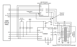
I have a design that uses a BQ25672 charger and a TUSB320LAI controller.

Previously my questions were answered on the BQ25672 portion by a terrific APPS engineer in the power management forum.

He recommended the Interface forum for questions on the TUSB320/BQ25672 combination.

Is there anyone who would be able to review the schematic and comment on the TUSB320/BQ25672 design?

Thanks in advance,

Dan

  • Hi Dan,

    Yes, there is!  Can you please send a link to the E2E post for the BQ25672?   Also, please submit your schematic.  

    Regards,

    Nicholaus

  • Hi Nicholaus,

    I'm not sure what link you wanted.

    I attached a pdf of the schematic page.

    Dan

    page2.pdf

  • Hi Dan,

    Thanks for the schematic.  I will assign to the correct expert.

    You said "Previously my questions were answered on the BQ25672 portion by a terrific APPS engineer in the power management forum."

    I was asking for a link to this forum post, but I believe this is it: (10) BQ25672EVM: BQ25672EVM - Power management forum - Power management - TI E2E support forums

    Thanks,

    Nicholaus

  • Hi Dante,

    I've attached my review of the TUSB320LAI as a pdf below. I have a couple questions to be sure I didn't miss anything.

    1. Are you using the TUSB320 as a DRP, DFP, or UFP? It seems that you're going for a dual role port (DRP) but I don't see how you control the VBUS.

    2. Why does the ID pin route to your connector? This pin is an output that goes low when the 320 is configured as a DFP or a DRP acting as a DFP. Usually this would control whether your device applies VBUS or not in a DRP application.

    3. Here is a useful reference for using the TUSB320 In a DRP application. This can be found in the datasheet's typical application section.

    4. I also recommend changing the pullup resistor on INT_N/OUT3 to 200K instead of 10K. This would model the typical application in the datasheet. I believe I forgot to add this in the review pdf.

    8015.320LAI review.pdf

    Best,

    Shane

  • Hi Shane, thank you for the review. See my answers below.

    1) I want to operate in DRP mode. When you say control the VBUS, you mean how do I source or sink power to the VBUS?

    I expected to use the BQ25672 in OTG mode to drive power onto VUSB2 if I want to be a DFP (Host)

    2) I was not sure what to do with it. Maybe it needs to goto my onboard processor that controls the BQ25672?

    3) Thanks I will review

    4) ok

    Questions:

    1) I'm not sure I understand how to use the port pin. Can I set the mode of operation with the I2C registers?

    The datasheet says PORT is an input used to indicate port mode. Maybe I NC to have DRP capability?

  • Hi Dante,

    When you say control the VBUS, you mean how do I source or sink power to the VBUS?

    That is correct. If you are using the BQ25672 to power VBUS then you would likely control the source/sink setting on this device with the ID pin from the TUSB320. 

    I was not sure what to do with it. Maybe it needs to goto my onboard processor that controls the BQ25672?

    The TUSB320 is intended for a USB-C port to negotiate DFP/UFP power delivery. The ID pin is an output from the 320 that is high by default, and will only go low when a UFP device is plugged in to the USB-C port. Here is a diagram to help show the behavior of ID.

    Maybe it needs to goto my onboard processor that controls the BQ25672?

    I think you are on the right track. Your processor could use the ID pin to control whether the BQ25672 is providing or sinking power from VBUS. Alternatively, you could read from the ATTACHED_STATE register in I2C.

    In either case, it would not make sense to route ID into your connector.

    Can I set the mode of operation with the I2C registers?

    Yes this is ok to do. By default, the 320 will read the voltage at the PORT pin to determine DFP/UFP/DRP. You can write to the MODE_SELECT register to change the role of your port in I2C. 

    I suggest keeping PORT NC to have DRP capability. This would make DRP your default setting, however it is ok to overwrite PORT in I2C as well.

    I noticed your connector (EN3P18F26PX) is not a USB-C connector. You would need to be sure the CC1/2 lines on the TUSB320 are connecting to the CC1/2 lines on the attached device through this connector.

    Best,

    Shane

  • Hi Shane,

    I think the plan is to have our local processor monitor the ID pin and react accordingly.

    We have an unusual connector due to the system we are building.

    We have a variety of adapter cables. For example we will have a USB-C to then EN3P18F26PX adapter.

    Then from there the USB-C we present can be a UFP or a DFP.

    Additionally, we could have an older USB-A to connect to.

    Do you see an issue with that type of connection?

    Dan

  • Hi Dante,

    Do you see an issue with that type of connection?

    It depends on what you want out of the USB connection. If you only need power delivery and USB2.0 data, then what you have is ok. The VBUS, CC1/2 pins, and D+/- pins can handle these use cases.

    If you need USB3.0 data rates, then you would need to dedicate 8 pins for the high speed differential pairs.

    Then from there the USB-C we present can be a UFP or a DFP.

    This is ok, as you would be configured for a dual role port.

    Additionally, we could have an older USB-A to connect to.

    This can work, keep in mind for a USB-A port, your adapter should handle the CC negotiation. USB-A does not have CC pins, so you would have to present the connected device as a UFP within the adapter.

    Best,

    Shane

  • Hi Shane,

    We do not need USB3 rates, and our onboard software will take care of CC negotiation, etc. I just want to have all the hooks needed to do any of these configurations. I've added a fuel gauge to the schematic, please give one final review if you can. (page 2)bridge-schematic-rev6-2024-01-18.pdf

    Thanks in advance,

    Dan

  • Hi Dante,

    I see that you still have the ID pin routed to the connector. Is there a reason for doing this?

    You've fixed the other issues I saw earlier. Aside from the ID pin, your schematic looks ok.

    One thing to be sure of is that the 3V3_LIN rail goes high before the non-failsafe pins on the 320.

    You can see which pins these are in the datasheet. In your schematic, let 3V3_LIN go high before VUSB2 or USB2_VBUS and there should not be a problem.

    Best,

    Shane

  • Hi Dante,

    I hope you are doing well. Is it ok to resolve this thread?

    I can answer any questions you still have on the TUSB320

    Best,

    Shane

  • Hi Shane,

    Some additional questions have come up.

    Can I contact you again?

    Should I contact via the forum or use email?

    Dan

  • Hi Dante,

    Our policy is to use the E2E forum for all support inquiries. We can continue using this thread.

    What questions did you have in mind?

    Best,

    Shane

  • Hi Shane,

    Please see attached document

    .TUSB320 related questions.docx

  • Hi Dante,

    ID will go low when attachment is detected on the type-C port and the 320 is configured as a DFP or a DRP acting as a DFP. This pin should be pulled up to VDD with a 200K resistor. ID is an output only pin.

    1. You need the 150uF capacitor enabled when configured as a DFP, not a UFP. You can see in the datasheet that the capacitor is disconnected when the 320 is a UFP.

    1a. You want to have the FET enabled when your device is providing VBUS. In the 320 datasheet, the VBUS switch EN pin is routed to control the FET to get this behavior.

    1b. I don't believe that diagram was made with a specific device in mind. An option you could consider is the TPS2547.

    1c. Yes, I recommend using ESD protection on these lines as they would be exposed to the outside world. 

    1d. The maximum capacitance allowed is 10uF if you are a DRP not sourcing VBUS.

    You seem to have 30uF of capacitance on the VBUS, which would be above the maximum set in the Spec.

    2. You would need to supply power to the TUSB320 if you want to keep the DRP functionality. When no device is attached it will remain in the unattached state, which should consume around 100uA.

    Considering the supply is 5V, this would be about 500uW of power in UFP mode.

    I am unsure what you mean by "how does the TUSB support this?". When you plug into a DFP, the TUSB320 will recognize the attachment and perform CC negotiation. When this is completed, the attached DFP will supply power on VBUS.

    If a UFP is attached, the TUSB320 will become the DFP and the ID pin will go low. You could try using this signal to wake your microcontroller in this case.

    By "the interrupt signal" are you referring to ID? ID will stay high until a UFP is attached to the port. You may be able to use ID to wake your microcontroller in the case where a UFP is attached, however this pin will remain high when a DFP is attached.

    The TUSB320 does not have a signal to indicate that a DFP has been attached. If the BQ256 can support that use case then that is where your interrupt would be sourced. If the USB deice plugged in is a UFP, then the TUSB320 ID pin will go low. Whether it is ok to use ID as an interrupt could depend on your microcontroller. Keep in mind that the ID should not be driven high/low by the controller, as it is an output only pin on the TUSB320. ID will go low when a UFP is attached to the port, and stay high in all other cases.

    3. The TUSB320-LA-EVM could work to evaluate the TUSB320. Keep in mind that the LA EVM would come with the TUSB320LAI device. This is essentially a newer version of the TUSB320.

    Best,

    Shane

  • Hi Shane,

    Eval board questions:

     Why doesn't the TUSB320LAI or TUS320HAI datasheets show the 150uF cap WITH the FET? (only shown in TUSB320 datasheet)

    What is the difference between the TUSB320 and the LA and HA versions? (just the enable?)

    What part should I be using? Since the LA is the newer version, I suspect I should use that device.

    It seems there is only one eval board with both the LA and the HA devices on it? Also, the eval board does not seem to have the 150uF cap for DFP usage?

    I have an eval setup for the BQ25672, before going to layout we wanted to experiment with a TUSB320 attached to the BQ eval board as much as is practical. Our goal is to try to fully understand what happens when a UFP or DFP mode is desired and how to handle it.

    Comments on numbered questions:

    1), 1a), 1b)

    What kind of FET arrangement do you recommend? An N-channel will not work. I think it has to be a P-channel with the source connected to VBUS.

    1c) I will use PESD5V0X1BL,315

    1d) I will lower the capacitance to 10uF.

    We are evaluating the (2) responses about interrupts, etc.

  • Hi Dante,

    Why doesn't the TUSB320LAI or TUS320HAI datasheets show the 150uF cap WITH the FET? (only shown in TUSB320 datasheet)

    The Capacitor is on the input of the VBUS switch in the diagram of the 320LAI/HAI datasheet. Ultimately, the implementation could be done either way. Having the capacitor on the output of the switch would bring it closer to the receptacle, giving it better placement for handling high frequency noise on the VBUS.

    What is the difference between the TUSB320 and the LA and HA versions? (just the enable?)

    You are correct that the difference between these devices is the enable polarity. The LAI and HAI versions additionally have a lower current draw than the original 320 (100uA --> 70uA in UFP mode) and the ID pin is failsafe, meaning this pin will not back-drive the device.

    What part should I be using? Since the LA is the newer version, I suspect I should use that device.

    I recommend using the newer LAI or HAI devices depending on whether you want a low-enable or high-enable pin.

    It seems there is only one eval board with both the LA and the HA devices on it? Also, the eval board does not seem to have the 150uF cap for DFP usage?

    You are correct that our TUSB320 EVM does not have the 150uF capacitor on the VBUS. I see there is a spot for a capacitor (C1) that could be populated with the value you need for testing. In your system you would want to control this capacitance to enable only when providing VBUS.

    What kind of FET arrangement do you recommend? An N-channel will not work. I think it has to be a P-channel with the source connected to VBUS.

    Using your MOS in the configuration shown in the datasheet would be my recommendation. I believe this is what you have in mind, with the source being attached to VBUS. You want to gate the MOS with a control signal that goes high when the VBUS is enabled. I know you are using the BQ25672 to enable/disable VBUS, however I am not familiar with this device. I can refer this thread to the team that supports the BQ25672 if you'd like.

    Best,

    Shane

  • Shane,

    What EVM should I buy:

    TUSB320EVM

    TUSB320-HA-EVM

    TUSB320-LA-EVM

    What is the difference?

    Is there another eval board needed? Like the HD3SS2522?

    I think the HD3SS25ss is obsolete?

  • Hi Dante,

    I recommend buying the EVM that correlates to the part you want to use. Since these are all different versions of the same device, the EVMs are identical. The difference would be the part that comes attached to the EVM.

    In my opinion, use one of the newer devices instead of the original TUSB320. Whether you want the LAI or HAI version is dependent on the EN pin being active high or active low.

    Is there another eval board needed? Like the HD3SS2522?

    I am unsure why you would need the HD3SS2522 EVM. That device is a superspeed MUX with a DFP-only CC controller integrated. With your application being a DRP that does not use the superspeed TX/RX lines, I do not believe the HD3SS2522 EVM would help you.

    Best,

    Shane

  • Hi Shane,

    One final set of questions regarding the EVM.

    I will buy the TUSB320-LA-EVM.

    I need to be able to test UFP (my board is a Device), DFP (my board is a Host) and DRP.

    Referring to the EVM datasheet please identify which figures apply to my cases?

    I'm not sure if  I need one or two EVMs to test all the modes of operation.

    Thanks,

    Dan

  • Hi Dante,

    You can test UFP, DFP, and DRP mode all on one EVM. Please refer to section 3 of the TUSB320 LA EVM users guide:

    This section has descriptions for configuring the board as a UFP (section 3.1), DFP (section 3.2), or DRP (section 3.3).

    Best,

    Shane