Other Parts Discussed in Thread: MAX3232,
Hi, TI expert
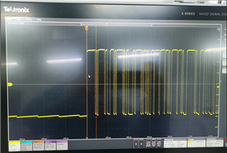
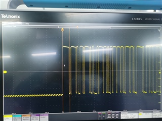
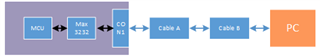
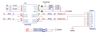
The figure below shows the serial port design of my MAX3232, The board is connected to the PC through the serial port cable A, and cable A is connected to the serial port to USB cable B and communicates with the PC. During the test, I found that there were noise glitches in the phase noise maps of some chips on the board, but after removing cable B(at this time, it could not communicate with the PC, the board card could still work normally), and connecting cable A to the board, there were no noise glitches in the phase noise maps of these chips.
I think it's the noise that goes from cable B to the board, so how do I design the protection circuitry on the MAX3232 to prevent noise from affecting the board's performance?
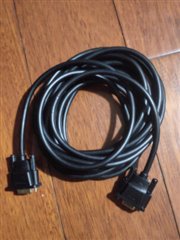 -cable A,
 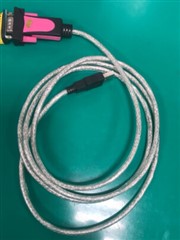 -cable B