This thread has been locked.

If you have a related question, please click the "Ask a related question" button in the top right corner. The newly created question will be automatically linked to this question.

DS90UB964-Q1EVM: Jumper placement J30 and J1 for 4 camera with 4-meter cable length

Part Number: DS90UB964-Q1EVM

Dear Sir,

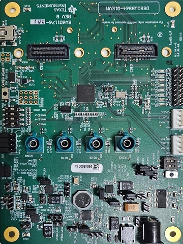
I have brought up the multi-camera( 4) with TDA4EVM and DS90UB964-Q1EVM.

I have done a few experiments 

cam 0, cam1,cam2 (Long 4-meter cables) and cam 3(short 10cm cable) this works fine

when

cam 0,cam1,cam2,cam3( All 4meter long cables) used , the application do not display anything.

Current J30 and J1 are set at below configuration:

J30 - Short pins:2-3 1.8V IO

J1 - Short pins:1-2 3.3V IO (default)

Rosenberger FAKRA connectors 4meter length

Sensor: ISX016 (Serializer DS90UB913xx)

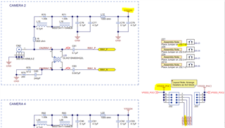
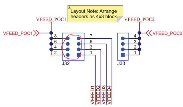
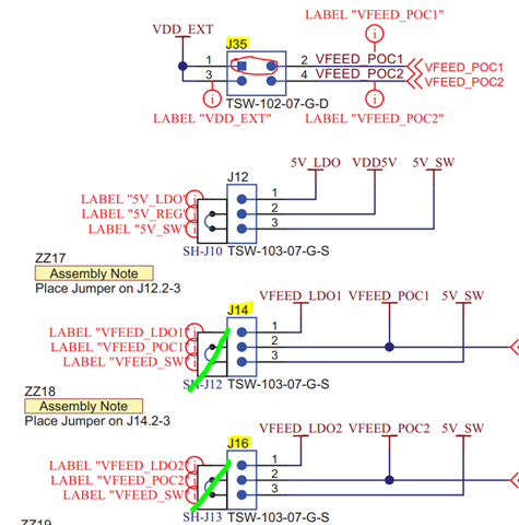
I would like to know the correct configuration of the jumper for both control interfaces and the role of them in power distribution in 4 cameras if it has any.

Thanks and Regards,

Vyom Mishra

  • Hello Vyom,

    Just to double-check,

    1. Is the only difference between your first test (Three long 4-meter cables and one short cable) and your failing test (All long 4-meter cables) the fact that you switched a cable for one of the RX Ports?
      1. Were the jumpers settings the exact same on both tests?
      2. Were the serializer sensors the exact same too?

    The default jumper options are defined in the 964 EVM user's Guide, starting at Table 1-3 and extending towards Table 1-16

    For PoC, J32 and J33 determine the source of the PoC voltage to the serializers.

    By default, VFEED_POC1 is the source. J14 determines the source of the PoC voltage, which defaults to 5V. Check J32, J33, and J14's jumper settings for PoC settings.

    Best,

    Justin Phan

  • Dear Justin, 

    Thanks for the quick response!

    1. a. Yes Jumper settings were kept the same for both tests

    1. b. Yes, the serializer sensors are all the same

     Check J32, J33, and J14's jumper settings for PoC settings.

    As we have configured the Deserializer in "Power Over Coax Power Feed using +12V Main Power (J21)" So J14 and J16 are left open (no jumpers are used)

    J32 and J33 are set as shown in Quick Start Guide 1.7

    For your reference, please find my Deserializer picture.

    Thanks and Regards,

    Vyom Mishra

  • Hello Vyom,

    Okay, so it seems the jumpers on J32/J33 are in their default positions, where VFEED_POC1 is used for the PoC voltage. 

    In that case, it is correct to not populate any jumpers on J14 and J16 if you populate the jumper across Pins 1-2 on J35.

    If all your jumper settings are correct, then the remote camera modules should be powered correctly. Some thoughts on what you can check below:

    1. When you replaced the short 10cm cable with a new 4meter cable, is there any chance that the new 4meter cable is faulty or excessively kinked/damaged?
      1. Do you still have LOCK active on all of the RX Ports?
    2. Are you outputting video data outputted from the TDA4EVM to a monitor, and see no video data on a screen? Or are you monitoring a status or diagnostics register? 
    3. Are you using a synchronized forwarding method on the 964 EVM, or Round Robin?

    Best,

    Justin Phan

  • Dear Justin,

    We have successfully brought up all the cameras with a 4-meter length cable.

    Thanks for your suggestions and response.

    Regards,

    Vyom Mishra