This thread has been locked.

If you have a related question, please click the "Ask a related question" button in the top right corner. The newly created question will be automatically linked to this question.

DP83822HF: Rx output have always same value from other phy or in pcs loopback

Part Number: DP83822HF

SIr, 

I try to make communicate two DP83822, but I always receive 0x5 on rx pins. 

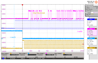
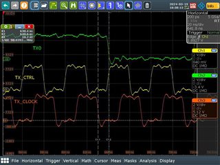
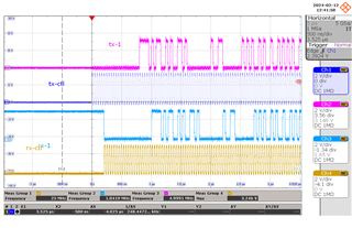
I tried to loopback with MII, and it works, I receive the frame I send (first picture).

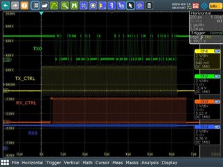
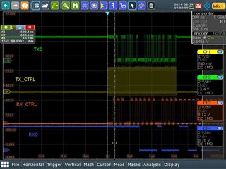
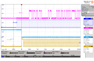
But when I try with pcs loopback, Rx pin are always on 0x5 value with Tx_ER at 1 on the two first nibbles. (second picture). I have the same behavior when I received data from other phy. 

I think PCS can't code or decode, but I don't know why.

I set this configuration : 

Disable_all_IRQ;
//Correct Strap pin config
//Disable FX, FPGA pin must sink current so strap not read correctly
ClearBit(this, CR2, FX_Enable_bit);
SetBit(this,BMCR,Speed_Selection_bit);
SetBit(this,BMCR,Autoneg_Enable_bit);
SetBit(this,BMCR,DuplexMode_bit);
SetBit(this, ANAR, Tx_100b_full_bit); //advertise 100Mbps
SetBit(this, ANAR, Tx_100b_half_bit); //advertise 100Mbps
ClearBit(this, ANAR, TXe_10b_full_bit);
ClearBit(this, ANAR, TXe_10b_half_bit);
//active rgmii
ClearBit(this, RCSR, RMII_Mode_bit);
SetBit(this, RCSR, RGMII_Mode_bit);
ClearBit(this, RCSR, RMII_Clock_bit);

ClearBit(this, LEDCR, LED_0_Polarity_bit);
//Enable auto mdi
SetBit(this, PHYCR, Enable_AutoMDI_bit);
ClearBit(this, PHYCR, Led_CFG_bit);
ClearBit(this, MLEDCR, MLED_Pol_bit);


SetBit(this, IOCTRL1, 0); //TODO refaire globale
ClearBit(this,IOCTRL1,1);
ClearBit(this,IOCTRL1,2);

ClearBit(this, EEECFG3,EEE_capabilites_bit);
ClearBit(this, EEE_ADV, Adv_EEE_100bps_bit); //clear energyefficient

ClearBit(this,RXCFG,WoL_Enbale_bit); //disable WoL

here screenshot for MII looppback
here with pcs loopback
I do same things with DP83xx811 and it works fine.

I must miss something and I try many configurations.

Could you give me some tips to try?

Thank you.

  • Hi,

    Can you please try another MAC facing loopback to confirm, such as Digital loopback?

    In normal communication (no loopback), do you see issues? Or only when PCS loopback is enabled?

    Sincerely,

    Gerome

  • Hi Gerome,

    I tried Digital loopback. The behavior is the same. 

    I also tried with data from another phy (normal communication with same configuration), the behavior on RX is the same. Link is up and autonegotiation is complete.

    Only MII loopback works.

    Sincerly

  • Hi,

    So MII loopback works, yet normal communication, PCS loopback, and Digital loopback fail. Can you please go through our DP83822 Troubleshooting Guide for additional debug steps? If this document proves to not be fruitful, we can further take up the conversation then.

    Sincerely,

    Gerome

  • Hi, 

    I have already gone through this document. 

    MDI signal seems to be good.

    Timing constrains are good, center aligned from FPGA.

    I can read and write through MDIO, reset_n is high.

    I force strap configuration with register and do a soft restart after.

    I will try again BIST mode (§2.7) tomorrow and check again register from §2.3, if ever I made a mistake there .  But never worked previously.

    But I have not the good voltage for RBIAS, I have 0.96v instead 2.7V. The resistor has the good value. All "VCC" pin are powered to 3.3v.

    Sincerely

  • Hello,

    Would it also be possible to utilize the PHY in reverse loopback to ensure that the MDI portion of the signal chain is not contributing to this issue? As the RX pins are outputs from the PHY, this would be taken from the MDI.

    Also, can you try continuity test on the RX pins against each other, against GND, and against VCC while the device is not powered? I want to check whether or not there is an unintentional short caused by assembly. Is this behavior present on these two boards only? On one of these boards? Or all boards you have created?

    Sincerely,

    Gerome

  • Hello, 

    I tried differents things. 

    First I use PRBS and Analog loopback : There is no error and PRBS generator runs and checker is lock and "sync", So Path PCS to MDI seems to be good.

    Secondly, I use PRBS on Phy1 without loopback, and I add reverse loopback on Phy2, same result. So MDI seems to be good. 

    On both situation, I have on RX some data but RX_CTL is still at 1. So there is no short with VDD or GND. 

    For memory, with MII loopback, I get back data I send on TX. I guess data are latched inside and not just wired to RX. I have between TX clock and data a hold of ~9ns and setup of ~10ns, larger than specification.

    So I guess, there is a misconfiguration between MII and PCS, but I don"t find what.

    Sincerely

  • Hi Stephane,

    I was talking to a colleague who had supported a similar query and he pointed out to this thread.

    https://e2e.ti.com/support/interface-group/interface/f/interface-forum/1298829/dp83822if-dp83822-phy-mii-internal-loopback-is-failing/4965122?tisearch=e2e-sitesearch&keymatch=dp83822%20loopback#4965122

    With this, I would like to focus in on functionality without loopbacks and PRBS as I feel that this complicates the debug. You had previously stated that normal operation shows the behavior. Have you checked out the continuity as mentioned before?

    How many boards are being affected by this?

    Sincerely,

    Gerome

  • Hi Gerome, 

    There is no poblem with contunity, I have data when I set MII loopback (see first post). I also check with multimeter.

    I try to shift RX Clk as explained in the query, it still does not work. The phase of RX Clk does not matter at this point because I probe signals with scope and not with the FPGA.

    I tried with a second board with the same results.

    When I use Phy in normal operation, I have RX_D always at 0x5 during communcaiton phase and the RX_CTL on the first two nibbles are in error as this figure.

    Pink and "dark" blue are TX_D1 et TX_CTL of the sender phy

    blue and yellow are RX_D1 and RX_CTL of the receiver phy

    Same result as if I used PCS loopback . So I suppose that PCS codes or decodes falsely

    Scrambler is locked

    Can you confirm me that TX_EN is latched on rising edge of clock and TX_ER on falling edge of clock for RGMII?

    I connected the board to my PC ethernet port to see what happens. I see data on RX_D0 but RX_CTL is at 1 during data phase as if all data were wrong.

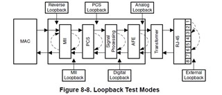
    In troubleshooting guide, the reverse loopback in just after PCS, but in Datacheet the reverse loopback is after MII, which one is the good one?

    Sincerely,

    Stef

  • Hi Stef,

    So you are stating that when link partner (Sender PHY) is getting data from MAC (pink), everything looks fine, but when it hits the DUT (blue), this completely is altered. 

    I am very curious if the data is being corrupted leading up to the PHY. Could you please send your schematics as well as check against our schematic checklist? If you have register access, can you also share register dump of 0x0-0x1F, as well as 0x421, 0x41F, 0x467, 0x468? Please note the last four registers are extended registers and thus need extended register access.

    0003.DP83822_Schematic_Design_Review_Checklist.xlsb

    Sincerely,

    Gerome

  • Hi Gerome,

    Please find Schematics here

    schematique.pdf

    Please note that components with red cross have been removed and NC means not connected. J1 is directly connected to FPGA.

    And here Register dump

    Please note that reg 0x15 change 0 to 0x36C and reg 0x05 change accordly 0x4181 to 0x6181..

    The two RJ45 are wired with an ethernet cable cat6.

    The frame is analyzed during transmission or we can send dummy (except for header)?

    Sincerely, 

    stef 

  • Hi Stef,

    Looking at the register dump, I have some concerns with the data provided;

    - Strapping indicates you are set up for 100Base-FX MDI with RGMII operation. However, the registers shown that correlate to this indicate that both RGMII and RMII are connected. Looking at the schematic, I believe you are wired up to the MAC with RGMII, but I am curious as to why the RMII enable bit is high on 0x17 with bypass FIFO.

    - Reg 0x15 indicates that the DUT is receiving invalid packets on the MDI; thus the packet is being corrupted before it even reaches the PHY. I would want to take a harder look at the link partner and potentially even switch the link partner with a PC just to eliminate this variable. This register should be 0 if the MDI pathway is clean.

    - I cannot check the magnetics, but I would want to ensure that these meet the datasheet specifications of the PHY. Please check the specs against the requirements using this FAQ.

    Sincerely,

    Gerome

  • Hi Gerome, 

    - For FX strapping, I set Mode 1 (FX_en = 0, PHY_ADD[0] = 0) but PHY read something else, may be there is a inside pull-up on FPGA pin because I do not use it for this case. So I force FX_EN to 0 with 0xA[14].

    - I bypass RMII Fifo for a try, because I saw that FIFO was overflowed. But no change whatever 0 or 1 for this bit. 

    - I tried to connect a PC with the DUT and I see data on RX_D but RX_CTL was always at 1 (on rise and fall RX clock) along with data.

    - Initailly, the link partner is the other PHY on the board, so same conception.

    - If Data was corrupted before PHY, I wonder why, when I send PRBS with Reverse Loppback back on the other PHYs, there is no error. Did I make a mistake?

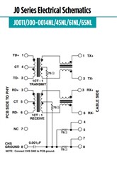
    - Here specifications for magnetics and RJ45. It is specified compliant with 100Base-TX.

    datasheet_j403-l_1699056699.pdf

    Sincerely, 

    Stef

  • Hi Stef,

    Regarding strapping and other potentially non-related configurations, it is recommended to have the PHY strapped accordingly to avoid other unforeseen registers toggle that users may forget to flip back; in general it is best practice.

    Magnetics look good; thank you for providing the information. 

    How did you initiate loopback on the DUT? In addition, on the LP, how did you determine that data was not corrupted? Since data would be coming through the link partner from the MAC, to the DUT and back up the chain, this would also validate the same MAC interface and PCS blocks that was of concern.

    Sincerely,

    Gerome

  • Hi Gerome, 

    Please see attached file for how I set loopback and results. Those were made in RGMII Mode.

    Loopback Explanation and results.pdf

    Secondly,

    I tried in MII Mode and it seems to work in scope signals. I have data.

    I have issue with timing constrains in FPGA I need to solve before to be sure of that.

    So the porblem seems to come from RGMII Mode configuration.

    Sincerely, 

    Stef

    PS: sorry for bad english

  • Hi Stef,

    Apologies for the delay. US was on Holiday at beginning of week.

    Let me take a deeper look into this data. Please expect a response by EoD Thursday at latest, but hope to get it out EoD today.

    No worries about the english =).

    Sincerely,

    Gerome

  • Hi Stef,

    Can you please try these two experiments to build upon your dataset? Please use all default configurations you would use during end case to prevent other debug variables previously implemented from compounding the issues. 

    1) DUT board in external loopback. This is using a loopback cable, which can also be made by cutting a Ethernet cable and shorting between pins: 1 & 3, 2 & 6, 4 & 7, and 5 & 8. This would short the TX and RX pairs together, to fool the PHY into linking up with itself. Have DUT's MAC send data through, and this will be a complete loopback testing out a board's MII and MDI robustness. If MAC indicates error free transmission, then this would indicate the issue may be interboard.

    2) DUT connected to LP in reverse loopback. This is using a regular cable for MDI, but the LP is in reverse loopback with the MAC sending data instead of PHYs PRBS. This would also test the entire signal chain of the DUT.

    Sincerely,

    Gerome

  • Hi Gerome,

    Sorry for delay, I was on another project. 

    I will do the tests you mentionned next week. 

    But If there are issues on board, why does it work when I communicate with MII format (Pin 3 only Enable, Reg0x17[9] = 0 and Reg0x17[5] = 0)?

    Sincerely,

    Stef

  • Hi Stef,

    That is a good question. I think there are many factors to consider when switching from MII to RGMII, which include control signal muxing, different signal timing requirements (setup/hold time), etc. Thus, it is important to conduct the prior experiments I was mentioning to isolate the MAC and board.

    If MII is working, is that a sufficient solution? 

    Sincerely,

    Gerome

  • Hi Gerome, 

    Sorry for delay. 

    The application must work in RGMII, but using MII at this step helps me to develop others parts. 

    I made a short on RJ45 connector, and I have the same behavior. 

    For Setup and hold, I have ~10 ns between data and clock on the pin of the device (center aligned).

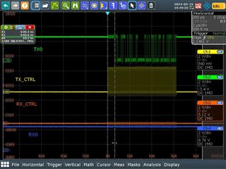
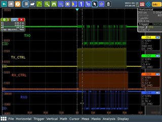
    But I tried again the MII loopback.

    And I see issues on this. Sometimes it works, I have data I sent back on RX pin but not always. 

    So I power up the device, write register and I have those three kind of signals, It alternates (without power down or rewrite registers). 

    The first picture seems the frequency is not good, the second nothing and the third is good. 

    I send 5 Frames in raw, and the 5 frames have the same behavior on RX. I make a "break" and  send the next 5 sames frames which have a different behavior on RX from the previous 5 frames (but same behavior for the 5 frames). So something appends between the "break".

    Do the frame content is important or the device doesn't care (wait for a frame size or CRC or...)? My frame are customed and not Ethernet compliant except header.

    Today, I will test if I have sometimes good communications because I rise a flag only in case of bad communication for now. I let you know when it is done.

    Sincerely, 

    Stef

  • Hi Stef,

    It does look promising that you are able to make the RX communication work with external MDI loopback. 

    When you mean frequency, do you mean of the TX_Dx line? For RGMII, a better tell-tale measurement would be of the RX and TX Clocks.

    I would like to understand more about how you made RX0 toggle. You stated that "I send 5 Frames in raw, and the 5 frames have the same behavior on RX. I make a "break" and  send the next 5 sames frames which have a different behavior on RX from the previous 5 frames (but same behavior for the 5 frames). So something appends between the "break"." You sent 5 frames in a row, which communicate fine on the RX. You then make a break (I assume in the packet) and send another 5 frames which then show the signature behavior. So without this break, the communication is fine?

    Frame content may have an effect as the device has been characterized for Ethernet compliant frames. If you were to force all of your data to be ethernet compliant data, would this behavior still show up?

    Sincerely,

    Gerome

  • HI Gerome, 

    Good news I found MY mistake. I found the information that CTL  must be at 1 on falling edge of the clock during normal operation.  

    For information the différent behavior above came from that I did not disable autonegotiation when I use MII loopback. 

    I want to thank you for your help and listenning. 

    Sincerely, 

    Stef

  • Hi Stef,

    Glad to hear everything worked out well! Happy to help!

    Sincerely,

    Gerome