This thread has been locked.

If you have a related question, please click the "Ask a related question" button in the top right corner. The newly created question will be automatically linked to this question.

SN65LVDS32: Around zero differential voltage, undefined state

Part Number: SN65LVDS32
Other Parts Discussed in Thread: SN65LVDS31,

Hello dear TI-support-team,

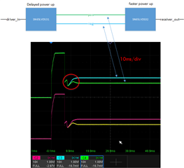
i have a LVDS-interface with a SN65LVDS31 driver and SN65LVDS32 receiver. I attached a picture of the block diagram and the oscilloscope measurement during power-up. The receiver turns on faster than the driver, so the receiver goes into fail-safe first. After that, we have this transition region (red circle) where the differential voltage is smaller than 100mV. Then the driver is activated and it drives the lines to its specified levels.

I have no possibility to measure the receiver out. Is it possible, that the receiver emits pulses on "receiver_out" because of the undefined state (red circle). In Datasheet section 10.4 (SN65LVDS32) it says: OUTPUT is "?" when differential voltage is between -100mV and 100mV.

Thank you

Best regards,

lyto
  • Hi Lyto,

    Thank you for your explanation and oscilloscope shot.

    If the receiver powers on faster than the driver, the differential input to the receiver briefly has no differential voltage present on the signal pair. This means that the case you mention above will fall in the "special case" category of the in section 10.3.1. Referring to section 10.3.2 and the device functional modes table 10.4, the device should have a valid high output.

    Regards, Amy

  • Thank you for the response. But I am not sure if this is really the case here. The cable is neither disconnected nor is the driver in high-impedance. It is a region where the driver power-up and takes control of the lines.

  • Hi Lyto,

    Since the receiver is connected but there is no driver output, the receiver sees the large impedance of the driver. However, from a datasheet perspective, this will fall within the indeterminate range (?). 

    You can overcome the internal fail-safe circuit with external biasing, using weak pull-ups / pull-downs to pull one differential line high and one low, to ensure that the device is in a known state. Ensure that the bias is not too great that the expected output from the driver cannot overcome it. 

    Regards, Amy