This thread has been locked.

If you have a related question, please click the "Ask a related question" button in the top right corner. The newly created question will be automatically linked to this question.

THVD1500: Emissions on RS485 Interface

Part Number: THVD1500
Other Parts Discussed in Thread: TIDA-01630

Hi, 

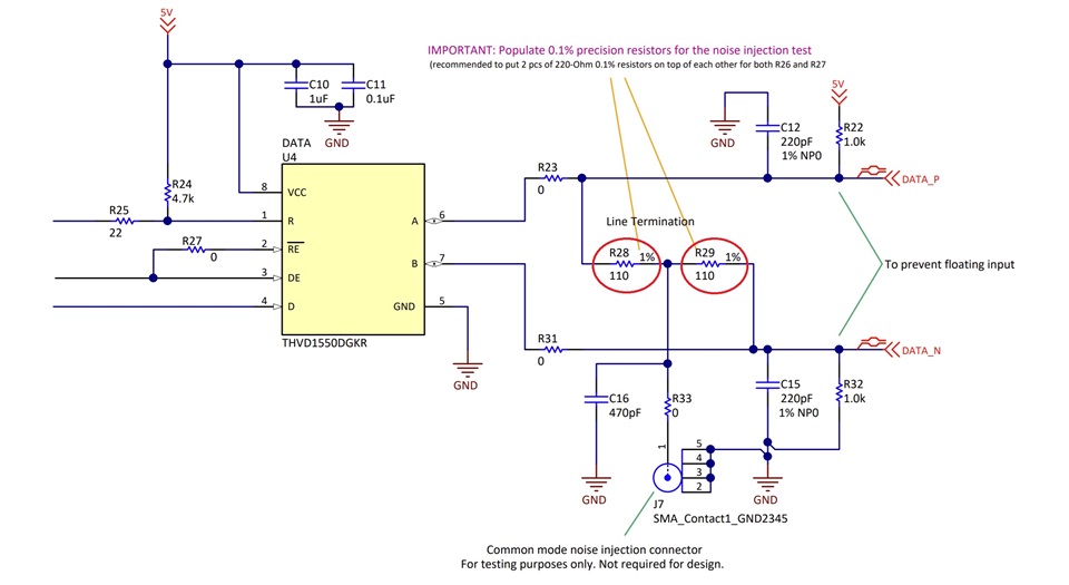
My question is regarding qualifications of THVD1500 device, or in general RS485 interface devices from TI with regards to conducted and radiated emissions. 

It seems like on RS485, the impact of radiated emission is minimized if a twisted pair is used, and that the output signal from these chips are fully differential. 

But how about conducted emissions? Are there concerns about qualification for conducted emissions on RS485 type interface devices? 

Please let me know, 

Thanks

  • Hi Kaveh,

    So we don't officially look into the emissions performance of RS-485 directly - but we do have some general guidelines and reasoning "why" we don't specify/test a lot in accordance with emissions standards.

    RADIATED EMISSIONS:

    So for radiated emissions there are generally 4 things that a properly setup RS-485 bus does to help prevent most radiated emissions issues. 

    1) As you noted - the differential structure of the output driver when used with a twisted pair cable does a lot of heavy lifting in terms of high frequency signal mitigation - which leads directly to lower radiated emissions in general. It should be noted that RS-485 standard doesn't specify a cable requirement  - but 120 ohm twisted pair is ideal in practice. 

    2) A properly setup RS-485 system will use 120 ohm cabling and both the start and end node should be terminated with a 120 ohm resistor. RS-485 buses at the data rates possible are considered transmission lines - so you have to consider impedance matching - the standard is very straightforward here - 120 ohm cable at a 120 ohm terminations in an ideal setup, neglecting component tolerance, will result in 0% of the incident signal being reflected back onto the bus. Generally speaking in practice this isn't perfect due to component tolerances  - but ideally it should be designed to minimize reflections - especially higher harmonic reflections as the THVD1500 specifically isn't really that much of a concern because its a slow device. 

    3) Any RS-485 bus signals that exist on a PCB (i.e. from IC on PCB to connector to cable etc...) should be differentially coupled, have the same length, have the traces as straight as possible from IC to cable connection point (they should be routed with high priority and treated like a high frequency transmission line as RS-485 can be considered high speed due to length vs. data rate possible)  and the characteristic impedance of the trace should also be 120 ohms. Deviations from this rule are more possible with slower devices like THVD1500 because the impedance mismatches/discontinuities on PCB are unlikely to be long enough to cause issue - but if you treat every RS-485 bus as possibly high frequency you will get better results for RS-485 design. 

    4) This one is a bit more tricky because the RS-485 standard technically doesn't talk about cabling and network topology  - but in a practical sense there are best practices to follow. Really when it comes down to it is that RS-485 allows more than 2 nodes on a bus - but only the start and end node are terminated (with 120 ohm resistors) - all the middle nodes are unterminated. It is assumed that the stub length (deviation from main trunk of bus) on the unterminated nodes are minimized - The max length depends on the propagation velocity of the cable Vp (common values typically are around 78% of c for 120 ohm cable)  and the differential transition time of the driver (lowest speed listed in datasheet is generally used - for THVD1500 that is 180ns) where the max unterminated stub length is L = tr,tf(min)/10 * Vp 

    So if we assume that Vp = 78% of c and tr,tf(min) = 180ns then the max unterminated stub length is approximately 4.2m. If your unterminated stub length is longer than that then the unterminated nodes will reflect high frequency signal back onto the bus during signal transitions - these reflections can possibly translate to radiated emissions if not handled properly. 

    Ideally this is mostly avoided if  you daisy chain the system as the unterminated stub length is minimized in that network topology. However other topologies (spine with junction boxes) can work but the stub length calculation needs to be adhered to.  

    Now with all that being said - even if all these factors are considered there may be need for even more additional components to help mitigate high frequency signals - as mitigating the high frequency signals on the bus is the best way to prevent those high frequency signals to radiate of off the bus. If that is a concern then usually adding filtering caps (single ended - i.e. A or B  to ground (I generally try to avoid these if possible as they load the bus) or differential B to A can be used), split terminations - that are commonly used in other standards like CAN, common mode chokes are not uncommon as well as possibly also ferrite beads. A lot of that stuff is added to prevent issues from signals coupling into the bus however - but can also be used to cut down on higher frequency content of data signal.  We do have a reference design on robust EMC design - while it doesn't use this exact IC a lot of the same principles can be applied universally to RS-485 systems (although some component values may change depending on what exact RS-485 device you are using is) 

    CONDUCTED EMISSIONS

    So in general we just don't really focus on conducted emissions - the main concern is usually radiated (long busses can act as radiator sources) - if anything conducted immunity is a bigger concern (which isn't really the same and the principles spoken about above are usually the same concepts we suggest there). 

    We do have a few reasons for this:

    1. There should be very little switching noise produced in the first place. When the driver is active it is constantly pulling current from VCC (RS-485 is a 4-switch driver which just changes the path of current from VCC and doesn't fully cut it off ideally (obviously in practice there is delay due to rise/fall times but both logic states are actively driven)) - while some switching could possibly be observed on the VCC pin - its generally not an issue especially if you are properly apply decoupling capacitors directly to the VCC pin as the switching noise should be relatively small (and for devices like the THVD1500 the base frequency of the input signal shouldn't exceed 250kHz). I have seen one or two systems implement a full EMI filter on the VCC rail - but generally because the power supply itself was noisy and that was to help get a "smooth" DC signal to the VCC pin. 

    2. It is generally assumed that RS-485 is used in conjunction with much noisier components. Generally the power supply, if a switching power supply is used (which is most common), will be generating way more concern w.r.t. to conducted emissions. This fact is compounded if things like motors also exist using the same base power source because they are the dominant concerns when it comes to conducted emissions - so generally the impact of the RS-485 device is negligible compared to other common elements that exist in an RS-485 system. 

    3. Conducted emissions are usually taken as a system level performance test - i.e. usually conducted emissions are taken as the summation of all devices that share a same primary source of power and a lot of solutions for conducted emissions are implemented at the boundary between system and main power (i.e. EMI filters between AC grid and rest of power tree in an industrial application). Generally this filtering needs to be considered due to the nosier components and generally the system level conducted emissions protection added will also cover any conducted emissions from RS-485 devices. 

    Essentially its not a problem we really ever see because the transceiver itself is generally outputting way less switching noise than the power tree and potentially electromechanical components and the same solutions for the noisier components also help reduce issues from the RS-485 device in general.

    CONCLUSION:

    Essentially most radiated emissions concerns are minimized through proper RS-485 bus setup - however additional filtering elements can be added to bus to further minimize high frequency signals that could possibly radiate

    Conducted emissions usually aren't a concern because there will generally already be some conducted emissions filtering in most systems that use RS-485 due to the power tree and/or electromechanical components that may exist and this filtering will also apply its benefits to any conducted emission generated by a RS-485 device (assuming that the power all originates from one source - usually direct to grid). Also it must be noted that proper supply decoupling also helps minimize any switching noise or oscillations that may occur on VCC pin of the rs-485 device. 

    Please let me know if you have any other questions and I will see what I can do!

    Best,

    Parker Dodson

  • Thanks Parker for the shared information. 

    In the manual that you shared "TIDA-01630", I can see that there are two 110 ohms resistors are used for termination of RS485. Shouldnt these resistors be 60 ohms so that the total termination becomes 120 ohms. Because having two 110 ohms makes the differential line impedance to be a total of 220 ohms. Please see attachment where I have circles these two termination resistors by a red.

  • The impedance of this termination is 220 Ω || (1 kΩ + 1 kΩ) ≈ 200 Ω. This should match the characteristic impedance of the cable, but the SERVO FD 798 CP datasheet is not very helpful, so I don't know if this is the case, but section 3.2.2.2 says:

    During these tests, it was seen that the choice of 220-Ω termination gives a poor eye diagram for industrial grade cables; the use of a 120-Ω termination on the drive side gives a better eye while using the cable in this report.

    When using a 120 Ω cable, you should indeed use a 120 Ω (= 60 Ω + 60 Ω) termination.

  • Thanks Parker. Can you please explain about this sentence that you wrote about conducted emissions: "1. There should be very little switching noise produced in the first place. When the driver is active it is constantly pulling current from VCC (RS-485 is a 4-switch driver which just changes the path of current from VCC and doesn't fully cut it off ideally".

    I am only interested to know about conducted emissions (150kHz-30MHz) and why it is not a concern in RS485 buses.

  • When the D input is high, current flows out of the A pin, over the bus and through the termination resistors, and into the B pin. When the D input is low, current flows out of the B pin and into the B pin. In both cases, it's the same amount of current, so switching the D pin has no effect on the power supply. (On toggling the DE pin would change the power consumption.)

    RS-485 used differential signals, i.e., as far as noise is concerned, the currents in both lines should cancel each other out. When needed, you can reduce common-noise further by adding common-mode chokes.