This thread has been locked.

If you have a related question, please click the "Ask a related question" button in the top right corner. The newly created question will be automatically linked to this question.

DP83848K: DP83848K Transformer question on inductivity

Part Number: DP83848K

Hi All,

I made a POE+/ Ethernet design with the DP83848 in conjunction with the Bourns SM42P01L. 

Checking the first Prototypes for ethernet, I found an issue with long cable runs. 

I made a eye diagram with lecroy WR640Zi and the testfixture and found that the eye is not

totally open.

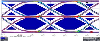
Seems to be a matter of rise times? and the crossings are moved. Its seems not that its a matter of

jitter (the crossings are quite small). So my gues is the difference in inductivity or/ and a higher DC resistance.

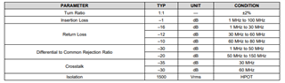
Double checked datasheet of phy and trafo, I found a difference in Inductivity of the

recommended trafos (350µH) and the inductivity of the bourns part (230µH).

As the recommendation in DP43... Datasheet doesnt give a hint on trafo inductivity, could this be an issue?

What else can I look at before I kick out the trafo?

Thank you in advance.

Joerg

  • Hi Joerg,

    Thank you for sharing the detail information. Based on the eye diagram, it seems your plot is right at the margin. The eye mask could be adjust to the right a bit to pass the compliance test. Yes, you are correct. Adding the DC voltage level on the center tap of the transformer will have an effect on the rising edge of the signal which will worsen the signal performance compare to non-PoE application.

    --

    Regards,

    Hillman Lin

  • Hi Lin,

    so it will get worse when poe is applied?  Is there a specification from ti for DP83848k transformer inductivity?

    Regards

    Joerg

  • Hi Joerg,

    Sorry for the confusion, I just realize we you are failing peak to peak on the eye diagram. Here are something I would recommend to test on:

    1. Could you double check on the characteristic impedance on the MDI traces lines? With smaller characteristic impedance on MDI traces will possibility result in higher peak to peak value which follow the observation you see below.
    2. Could you double check on the MDI traces length?
    3. Could you double check on the transformer specification make sure it follow the datasheet requirement. This would also effect the peak to peak value of signal.
    4. Could you also double check on the pull up voltage of VDD on both MDI lines or center tap. Make sure the VDD voltage is not overshooting.

    I also have layout checklist that could help you.

    2742.IndustrialPHY_Layout Review Checklist.xlsx

    Regarding to the transformer, please take a look on the following specification:

    --

    Regards,

    Hillman Lin

  • Hi Hillman, 

    thank you.

    1. Could you double check on the characteristic impedance on the MDI traces lines? With smaller characteristic impedance on MDI traces will possibility result in higher peak to peak value which follow the observation you see below.
    2. Could you double check on the MDI traces length? ==> will be optimised in next layout
    3. Could you double check on the transformer specification make sure it follow the datasheet requirement. This would also effect the peak to peak value of signal. ==> parameter are ok, but Phy datasheet doesnt give a hint for inductivity.
    4. Could you also double check on the pull up voltage of VDD on both MDI lines or center tap. Make sure the VDD voltage is not overshooting. ==> is ok

    I also have layout checklist that could help you.

    2742.IndustrialPHY_Layout Review Checklist.xlsx

    ==> great, thanks, checked and seems to be ok. It seems to be only a problem with the parameter of the transformer, as when I change the trafo as with 350µH one, I will get a nice eye.

    Regarding to the transformer, please take a look on the following specification:

    ==> again, no hint for inductivity and no remarks for DC resistance.

    I will do another check with a 120µH trafo, with a classictoroidal core, Iam really curious about it.

    Any other hints/ ideas on this?

    Best regards,

    Joerg

  • Hi Joerg,

    Thank you for pointing it out

    I double check with the team internally. 350uH is always the recommended value for the inductance. We will fix that in the new revision of datasheet.

    --


    Regards,

    Hillman Lin

  • Hi Hillmann,

    can you confirm, that a lower inductance can lead to this behavior? Can you sugest a Phy that can cope with smaler inductance as for instance 120µH or 230µH?

    Best Regards.

    Joerg

  • Hi Joerg,

    Yes, the lower inductance will lead to this behavior for the transformer. 350uH is recommended inductance value for transformer.

    --

    Regards,

    Hillman Lin